Continue to Site

Welcome to EDAboard.com

Welcome to our site! EDAboard.com is an international Electronics Discussion Forum focused on EDA software, circuits, schematics, books, theory, papers, asic, pld, 8051, DSP, Network, RF, Analog Design, PCB, Service Manuals... and a whole lot more! To participate you need to register. Registration is free. Click here to register now.

Anolog Comparision - Resistor ladder circuit

Status
Not open for further replies.

jey11

Newbie level 5
Joined
Mar 3, 2011
Messages
9
Helped
0
Reputation
0
Reaction score
0
Trophy points
1,281
Activity points
1,334
Hi,
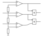
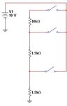
I need to build a function box for testing switches(Resiter ladder).
One input 2V or 6V or 8V .
The output should green led for 2V input.
The output should red led for 4V input.
The output should yellow led for 8V input.
All off for no input is selected.
How can I do this? Please help me out.

Jey
 

HI. You just use three independent comparators to do that.
 

Attachments

  • 3comparators.png
    3comparators.png
    4.7 KB · Views: 124

I tried It didn't work as it suposed to be.

for ex:
For 2V.. I compare with Vref= 1.5 if it is true turn on green led.
For 4V.. I compare with Vref= 3.5 if it is true turn on Red led and green led
For 8V.. I compare with Vref= 7.5 if it is true turn on all leds.

look like I am missing some logic here..

Only one common input is available...
 

Hi. Use some simple logic gates between the comparator outputs to make only one output be active at a time.
 

Attachments

  • 3comparators_logicGates.png
    3comparators_logicGates.png
    8.2 KB · Views: 151
  • Like
Reactions: jey11

    jey11

    Points: 2
    Helpful Answer Positive Rating
Thanks for your help
 

attached is the actual switch.

Thanks
 

Attachments

  • Switch.JPG
    Switch.JPG
    8.8 KB · Views: 135

Status
Not open for further replies.

Part and Inventory Search

Welcome to EDABoard.com

Sponsor

Back
Top