Continue to Site

Welcome to EDAboard.com

Welcome to our site! EDAboard.com is an international Electronics Discussion Forum focused on EDA software, circuits, schematics, books, theory, papers, asic, pld, 8051, DSP, Network, RF, Analog Design, PCB, Service Manuals... and a whole lot more! To participate you need to register. Registration is free. Click here to register now.

Analogue voltage detector

Status
Not open for further replies.

mondo90

Junior Member level 1
Joined
Oct 26, 2014
Messages
19
Helped
1
Reputation
2
Reaction score
1
Trophy points
3
Activity points
151
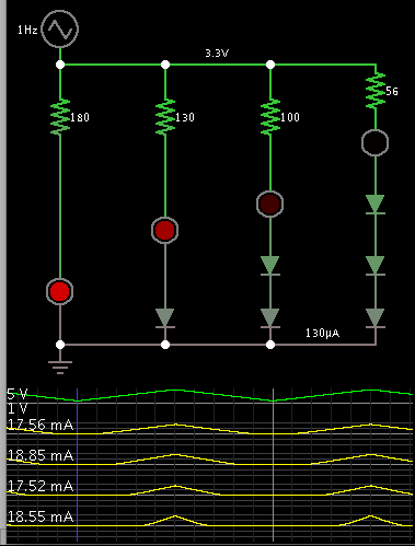
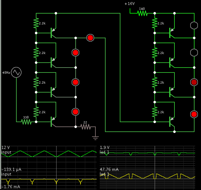
Hello, I am looking for circuit which is able to detect voltage changes without help from chips. Let's say I want to turn on diodes accordingly to voltage magnitude, voltage is low - one of four diodes is on . With help of microcontroller and ADC it is simple, can be done without micro... ?

Thanks.
 

uC is not necessary..
After a proper ADC ( Parallel Output ) you may use a Programmable Decoder ( or simply Gates Decoder) to obtain "Flags" for your circuit.
Flags means that when digital words ( bytes ) have wanted value a flag is move up and excite the other circuit.
 

Better still, use comparators. You can make them out of discrete components but it's much easier with dedicated ICs. Just set a trip point for each of the diodes (I assume LEDs) to turn on and as the analog voltage passes it the corresponding LED lights up. If you want them to be exclusive, only one at a time lit up, you need some additional logic to prevent ones lower than the highest one lighting or you can use 'window' comparators that only light the LED when the voltage is between two thresholds but not above or below them. The danger with window comparators is that if each window range doesn't exactly meet the next one, you get gaps when no LED is lit or two at once light if the ranges overlap.

Brian.
 
Let's say I want to turn on diodes accordingly to voltage magnitude, voltage is low - one of four diodes is on

If sufficient current is available then you can make led's into a bargraph.

7077766900_1414457240.png


You can also tap at a point between diodes, and apply it to control a transistor, etc.
 

Interesting, it's a pity it needs more than the sum of LED Vf and Vbe as minimum supply voltage.

Another alternative would be several transistor drivers, each ground referenced with a LED in their collectors but with different numbers of diodes in each base to set the thresholds. It would be easier to ensure saturation and need a lower supply voltage. I can see why the design in the link did it that way though, it's a clever way of using the outputs to control the step size through the 'A' and 'B' feedback points. It does use a constant current sink in the LED chain though which the simulation ignores.

Brian.
 

If sufficient current is available then you can make led's into a bargraph.

7077766900_1414457240.png


You can also tap at a point between diodes, and apply it to control a transistor, etc.

You can also increase sensitivity and range by putting above into an NPN collector powered by 9V with a high gain negative feedback circuit, self-biased so the string lights up according to the amount of change of input voltage in AC or DC , with optional input gain pot.
 

Thank you all for good ideas ;)

uC is not necessary..
After a proper ADC ( Parallel Output ) you may use a Programmable Decoder ( or simply Gates Decoder) to obtain "Flags" for your circuit.
Flags means that when digital words ( bytes ) have wanted value a flag is move up and excite the other circuit.

Hmm, I kinda don't get it, can you recommend any resource on this or explain it in a little more detail way?
 

Forget electronics and buy cheap analog panel meter. It works without power supply and you will measure voltage instead indicate it by LED. You can get it for few dollars with free shipping.
 

Status
Not open for further replies.

Similar threads

Part and Inventory Search

Welcome to EDABoard.com

Sponsor

Back
Top