Continue to Site

Welcome to EDAboard.com

Welcome to our site! EDAboard.com is an international Electronics Discussion Forum focused on EDA software, circuits, schematics, books, theory, papers, asic, pld, 8051, DSP, Network, RF, Analog Design, PCB, Service Manuals... and a whole lot more! To participate you need to register. Registration is free. Click here to register now.

Amplification of 74AC14 square wave output

Status
Not open for further replies.

kicom

Junior Member level 1
Joined
Mar 31, 2012
Messages
17
Helped
0
Reputation
0
Reaction score
0
Trophy points
1,281
Visit site
Activity points
1,410
Hi,

Currently I'm developing a square wave form of 1MHz using 74ac14 schmitt trigger ic.
I have faced major problems in doing so as follows.

1. The square waveform get distorted after 200kHz
I have tried to address the 1st one with using 555 timer and xp2206 ic.But they are even worse above 100kHz.

2. The duty cycle is not 50% as said in datasheet
The duty cycle is not close to 50% even after I used a diode and a resistor to solve the problem

3. How to amplify the output to about 12v
What are the available amplifiers which can amplify the output of 74ac14 (about 5v) to 12v.
Would it be possible to amplify such high frequency waveform.

Thanks
 

Do you have to use specifically the 74AC series? Can you employ the HC or HCT series instead?

Could you post your circuit with values?

- - - Updated - - -

Do you have to use specifically the 74AC series? Can you employ the HC or HCT series instead?

Could you post your circuit with values?
 

Do you have to use specifically the 74AC series? Can you employ the HC or HCT series instead?

Could you post your circuit with values?

- - - Updated - - -

Do you have to use specifically the 74AC series? Can you employ the HC or HCT series instead?

Could you post your circuit with values?

Thanks for the reply.
Actually what i have tried on the board is HD74LS14 IC. Which is quite similar to AC14 but the rise time is 10ns higher in LS14.The commonly available DIP ic in our country is LC14.Others are SMT ones.That's why i used that.
Is there any particular reason to use HC or HCT ????

From my research in the internet i have found the relationship with output frequency of schmitt trigger is 1.2/RC and duty cycle is 50%.
But my experiments shows the constant quite different from 1.2.And duty cycle about 60% after using the diode.Unless it will be around 75%
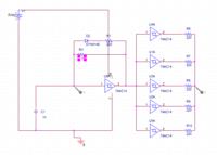
This is my circuit generating 530kHz


But
 

You would probably do better to use two of the inverters in the oscillator. I would guess your problem at 1MHz is the time and current needed to charge the 1nF capacitor, try dropping it to say 100pF and adjusting the resistor values accordingly.

To increase the output voltage you need a higher voltage supply of course but you should be able to use the signal from a few parallel inverter sections to saturate a transistor and get a fairly good 'square' wave output.

Brian.
 
  • Like
Reactions: kicom

    kicom

    Points: 2
    Helpful Answer Positive Rating
First check you are not overlooking the obvious.

1) Decoupling cap. next to chip across supply.
2) short leads to reduce inductance of wires try to get < few cm max on all leads
3) for ideal fast rise time waveforms avoid using scope probe with tip and gnd clip, instead use pin and barrel instead.
4) choose small cap to reduce drive current < max current at specified slew rate Ic=C*dv/dt

Suggest using any CMOS Schmitt trigger rated to operate at 12V will easily work with 1K Ohm and 100 ~250 pF.
 
  • Like
Reactions: kicom

    kicom

    Points: 2
    Helpful Answer Positive Rating
Dear betwixt,
;1416317 said:
To increase the output voltage you need a higher voltage supply of course but you should be able to use the signal from a few parallel inverter sections to saturate a transistor and get a fairly good 'square' wave output.

Brian.

How can you amplify the with a saturated amplifier and some parallel inverters.i can't understand how it is possible in saturated state.

- - - Updated - - -

Dear sunnyskyguru,

Your post certainly helped me.I was not aware of the high voltage schmitt triggers.But the circuit will have to be change.right??
 

Dear sunnyskyguru,
Your post certainly helped me.I was not aware of the high voltage schmitt triggers.But the circuit will have to be change.right??

No. Same 14pin pattern. Maybe different RC value.

Did you fix the noise problem yet with short grounds on probes and layout?
Twisted pairs on long wires etc. decoupling caps...
 

Parallel inverters work in unison but give more output current. 2 inverters can give twice as much current, 3 gives can give three times and so on. If you parallel all the unused inverters at the output you will get more output current capability. The extra output capability allows it to charge and discharge load capacitance faster (= squarer edges) and ensure it can fully drive a transistor B-E junction into saturation. You can then produce almost any voltage you want by using the transistor as a switch to ground with a pull-up resistor to the voltage you need.

As SunnySkyguy points out, the extra current as the device changes state will make good supply decoupling mandatory.

Brian.
 

Status
Not open for further replies.

Similar threads

Part and Inventory Search

Welcome to EDABoard.com

Sponsor

Back
Top