Continue to Site

Welcome to EDAboard.com

Welcome to our site! EDAboard.com is an international Electronics Discussion Forum focused on EDA software, circuits, schematics, books, theory, papers, asic, pld, 8051, DSP, Network, RF, Analog Design, PCB, Service Manuals... and a whole lot more! To participate you need to register. Registration is free. Click here to register now.

Alternative to a bunch of 555 timers

Status
Not open for further replies.

steven834

Newbie level 6
Newbie level 6
Joined
Dec 10, 2014
Messages
14
Helped
0
Reputation
0
Reaction score
0
Trophy points
1
Visit site
Activity points
106
I have (about 22) momentary SPST switches which I want to control corresponding relays ( And I want the relays to fire for 3 seconds).
I saw a one shot monostable multivibrator circuit Consisting of a 555 and two resistors and two capacitors.
So 22)555s and 44) resistors and 44) capacitors should do the job nicely.
My question is can I do this another way using fewer components and easier assembly?
 

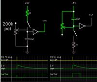
You can do the equivalent with one capacitor and a logic gate (example, inverter).

This simulation shows two ways to operate the switch. It depends on whether you want the pulse to go positive for 3 seconds, or negative for 3 seconds.


The 30 ohm resistors are unnecessary. They were added so that switch presses show up properly on the scope trace.

If you use logic IC's containing multiple gates, then you can condense the entire layout. (Example, 4049 or 4069 hex inverters.)

There might be a problem driving your relays directly from logic gates. A 555 IC can supply 200 mA. Logic gates may or may not supply sufficient current.
 
U can opt for a micro controller like 89S52 OR PIC16F877 which can do all what u have written. You need to write a code for it. Thatz it. If you are intending to use only one Micro-controller you you may use a keypad encoder IC like the 74LS922 to take inputs from the switches and 4 outputs data bus can be connected to a Port 1 and rest 3 ports can be used as output for relays. OR you may use one micro as switch controller whereas other to control the relays.
Cheers
 
I would start with some thing like a ULN 2803 ( https://www.sparkfun.com/products/312 ). This should drive your relay OK and hang capacitors on its input like the above example.
Frank
 
Regarding the relay it should be able to drive .5 amp at 5V on the contact side I think maybe I’ll use a small reed relay like HE721A0510.
And I think I’ll use the ULN2803 instead of the 4069 hex inverter because the former has more gates per package( eight as opposed to six).
My question is regarding the 200K potentiometer BradtheRad put in his drawing,
Could you give me resistor and capacitor values to close the relay for about 3 second (plus or minus half a second). Or should I just figure it out with the pot?
 

My question is regarding the 200K potentiometer BradtheRad put in his drawing,
Could you give me resistor and capacitor values to close the relay for about 3 second (plus or minus half a second). Or should I just figure it out with the pot?

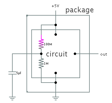
In a real circuit, all or some of the resistance might be in the input of the following device. My simulation portrays only the bare concept of how the RC discharge creates a delay.

For instance, suppose the input impedance is 1M ohm (a typical figure). Then you do not need to add an external resistor or potentiometer. You need only attach a capacitor.

A suitable value in that case is 5 uF. It will discharge through the 1M input impedance, dropping from 5V to 2.5V in 3 seconds.
 

I don’t understand. Are you talking about the input impedance on your oscilloscope?
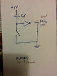
Or are you saying I can build the circuit with no resistor as pictured?
UNL2803.jpg
 

I don’t understand. Are you talking about the input impedance on your oscilloscope?
Or are you saying I can build the circuit with no resistor as pictured?
View attachment 112246

Devices have some internal impedance at the input pin. The resistance is inside the circuitry.

Usually it is from the input pin to ground. Sometimes you can measure it directly (although it might be difficult to measure in the case of FET-inputs).

5545202400_1418329407.png


This internal impedance may or may not be usable for discharging your capacitor. You may find it is very high ohms to the positive supply. The only way to find out, is to experiment.

I mentioned the idea because if it works then you can conserve space and parts count.
 

Regarding the relay it should be able to drive .5 amp at 5V on the contact side I think maybe I’ll use a small reed relay like HE721A0510.
And I think I’ll use the ULN2803 instead of the 4069 hex inverter because the former has more gates per package( eight as opposed to six).
Regarding the ULN2803, it has several problems.

1. It is a Darlington, which means the saturation voltage is two diode drops above ground, or about 1.6 volts in your case. So if your relay was expecting 5 volts and was being driving by a 5 volt supply, that relay will only see 3.4 volts when the switch is on, which is not high enough for the 5-volt relay you want to use.

2. The input structures are bipolar transistors that require 1.35 ma. to turn on. This will make it harder to construct a 3-second RC network on the inputs. Using the 22 uF cap recommended by BradtheRad, this 1.35 ma. current would produce a change of 61 volts per second. Since you only have a few volts to play with, you cannot sustain this level of discharge for 3 seconds. To reduce the voltage change to a manageable .5 volts per second, you would need a capacitor of 2700 uF, which is a huge device. Also getting a charge into this device through a pushbutton would burn out the contacts on the switch.

So if you are going to use the ULN2803, you would have to:

1. Provide a relay supply voltage that is 1.6 volts higher than the rated relay voltage.
2. Use a separate hi-Z (CMOS) buffer on the input so reasonable RC time-delay components could be used.

Personally, I would go with the microcontroller solution suggested earlier.
 

Technically you don't need a logic gate at all, simply use the switch to charge up a capacitor, and then discharge that capacitor through the relay's coil. When the capacitor discharges through the coil, its voltage will drop and when the current drops below the holding current of the relay it will disengage. So aside from the switch, only a single capacitor is needed.
 

that sounds logical. so why are there all these one shot monostable multivibrator circuit passing through logic gates?
 

Does using the 4049 or 4069 hex inverters avoid the Darlington problem?
Yes, it's CMOS. As long as it can sorce or sink sufficient current for the relay coil.

- - - Updated - - -

Technically you don't need a logic gate at all, simply use the switch to charge up a capacitor, and then discharge that capacitor through the relay's coil. When the capacitor discharges through the coil, its voltage will drop and when the current drops below the holding current of the relay it will disengage. So aside from the switch, only a single capacitor is needed.
Since the relay coil requires even more current than the 1.35 mA I discussed earlier, it will require a gargantuan capacitor to do this directly. While theoretically possible, it is not cost- effective.
 

Does using the 4049 or 4069 hex inverters avoid the Darlington problem?
Why not look at the datasheet for the CD4069 hex inverters IC? When it has a 5V supply its minimum output current is only about 1.5mA. It can drive a ULN2803A. The input resistance of the CD4069 is infinite so you would use a high value resistor to slowly charge or discharge a fairly small capacitor.

The CD4069 does not suddenly switch so it might not be suitable. Instead you can use a Cmos Schmitt Trigger inverter like a 74C14. If your relay draws 25mA or less then you can use a 74HC14 which is a more powerful Cmos logic IC that can drive it directly.
 

I would use a cheap microcontroller with sufficiant number of output pins. i ran into a similiar situation some time back where i had the choice of having a combinational circuit with many ics and many inputs and outputs and the best way i could solve it was using a microcontroller. you can also use a microcontroller with few pins by using an additional multiplexer and Registers
 
Status
Not open for further replies.

Part and Inventory Search

Welcome to EDABoard.com

Sponsor

Back
Top