Continue to Site

Welcome to EDAboard.com

Welcome to our site! EDAboard.com is an international Electronics Discussion Forum focused on EDA software, circuits, schematics, books, theory, papers, asic, pld, 8051, DSP, Network, RF, Analog Design, PCB, Service Manuals... and a whole lot more! To participate you need to register. Registration is free. Click here to register now.

[SOLVED] Alternative for SSRs

Status
Not open for further replies.

ankitvirdi4

Member level 4
Joined
Mar 13, 2012
Messages
70
Helped
4
Reputation
8
Reaction score
4
Trophy points
1,288
Location
India
Activity points
1,925
Hello,

I basically have project part of which requires to switch a 100mA load which can be 5 to 230VAC or 5 to 300V DC.

The load is supposed to turn on and off say 10 times a second, like a square wave.

I need to isolate the load from the primary circuit

So SSRs are perfect for the application, only they are very expensive.

Is there an alternative?

Can I use miniature reed relays given they will continuesly be switching a load?
 

An SSR is probably the optimum part to use. Assuming your AC is 50Hz or 60Hz, each cycle lasts 20mS or less so if you turn it on and off 10 times per second, you have no more than 50% of one tenth of the time to enable the power, that only gives you a few mS in each burst. If you use a mechanical switch, whether reed or conventional relay, the time taken for the contacts to move will be significant and cause a large loss.

You might be able to use opto-MOSFET switches as an alternative but I'm not sure you can get ones that can switch such high voltages. Possibly using the two in parallel will work, the MOSFET ensuring low loss at low voltages and the SSR doing all the hard work at higher voltages.

Don't forgret you can make your own SSR from a pair of SCR's and an opto-coupler, it might be cheaper than a ready made unit.

Brian.
 
Hi Brian,

Thanks for the insight.

Say I make SSR using optocoupler and SCRs, how do I switch DC load with it?
 

Switching on a DC load with an SSR is the same as if it was AC, the problem would be switching it off because it would kep conducting until the voltage across it was removed. Three methods come to mind:

1. Use SCRs and a parallel MOSFET then sense whether AC or DC was being used. For AC use the SCRs, for DC use the MOSFET.
2. Use the SCRs for AC and DC but pulse the MOSFET to pulse 'short out' the SCR's just before switch off is wanted.
3. Use SCRs for both but use a commutation circuit to remove the voltage when you want to switch them off.

Method 3 works by sampling the voltage across the SCR then pulsing it back with reverse polarity to cancel it and hence stop the SCR conduction.

The bigger problem with SCRs is the low voltage you may want to switch, each SCR will drop some of the voltage so when it's as low as 5V you could lose a substantial amount of it. The parallel MOSFET idea will place a resistive element in parallel with the SCR so the voltage drop would be much smaller but as I stated earlier, you would then need a device capable of withstanding the highest voltage (~350V peak) instead.

I haven't tried it but you could in theory use two MOSFETS, each with a series Schottky diode so one conducts on positve half cycles and the other on negative half cycles. It would still drop some voltage but it would be much lower than SCRs. The problem then becomes one of controlling the MOSFETs as their control voltage has to be relative to their source pins which could be at anything between about +5V and -350V.

Brian.
 
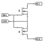
As per your suggestions I am planning something on these lines.

mosfet.png

Which you said should work in theory,

I think this part would work ?

https://www.farnell.com/datasheets/2007680.pdf

Driving through an optocoupler to isolate the logic, I somehow need to figure out how to use the load voltage itself to bias the optocoupler transistors.

Do you think this will work?

P.S: Edit , I realise there is no schottky diode in the picture.
 

It should work but beware of one issue: in each polarity, one MOSFET conducts normally and the other is cut off, the current flows through the PN junction between it's drain and source. It means you can model it as a MOSFET switch in series with a silicon diode so there will always be a voltage drop (called VDSF in the data sheet) plus a little due to RDS resistance of the conducting device. You can never get out what you put in so it isn't a perfect switch, especially at low voltages where the drop is proportionately more of the total.

Brian.
 
Use a Vishay VOM1271 Photovoltaic MOSFET Driver with Integrated Fast Turn-Off.

Designed specifically to drive Mosfet Solid-State Relays.

It is isolated, and since it generates its own voltage, you don't require an isolated bias supply.
 
Status
Not open for further replies.

Part and Inventory Search

Welcome to EDABoard.com

Sponsor

Back
Top