Continue to Site

Welcome to EDAboard.com

Welcome to our site! EDAboard.com is an international Electronics Discussion Forum focused on EDA software, circuits, schematics, books, theory, papers, asic, pld, 8051, DSP, Network, RF, Analog Design, PCB, Service Manuals... and a whole lot more! To participate you need to register. Registration is free. Click here to register now.

[SOLVED] ADS1118 Temperature Sensor value not Correct??

Status
Not open for further replies.

xpress_embedo

Advanced Member level 4
Joined
Jul 5, 2011
Messages
1,154
Helped
161
Reputation
396
Reaction score
189
Trophy points
1,353
Location
India
embeddedlaboratory.blogspot.in
Activity points
10,591
Hello!! I am using ADS1118 with atmega2560 micro-controller, to sense its internal temperature.

But i tried each and every method, but in all cases i am getting very large temperature values.


Code C - [expand]
1
2
3
4
5
6
7
8
9
10
11
12
13
14
/*
 * Config Bytes to Read Internal Temperature
 *
 * SS = 1 (single-shot) - NOTE: Always reads back as '0' (default).
 * MUX = 000 (default)
 * PGA = 010 (full-scale is +/-2.048V)
 * MODE = 1 (power-down and single-shot, default)
 * DR = 100 (128 samples per second, default)
 * TS_MODE = 1 (read from internal temperature sensor)
 * PULL_UP = 1 (pull-up enabled)
 * NOP = 01 (must be 01 to update the Config Register, no-operation otherwise) 
 * NOT_USED = 1 (not used, always reads 1)
 */
#define TC_TEMP         0x859B    // the Config bytes to read the internal temperature from ADS1118


The above is my configuration register and the values i am obtaining are as follow:-
DA8 = 3496 which on multiplication 3496 * 0.03125 = 109.25 deg C
D7C = 3452 which on multiplication 3452 * 0.03125 = 107 deg C

I am doing something wrong in calculation.

- - - Updated - - -

************************************************************************

I saw post on this forum.

https://e2e.ti.com/support/data_converters/precision_data_converters/f/73/p/231496/835608#835608


Code C - [expand]
1
2
3
4
5
6
7
8
9
10
if(step==0)
        {
                    SPIWrite(0x08);
                    SPIWrite(0xA2);
 
                     res=(data_high<<8)|data_low;
                     res = res>>2;
                     Res_val=res * 0.03125;
                     refTemp = Res_val;
         }


Why shifted two times.


Code C - [expand]
1
res = res>>2;


If i shift my data two times, then it will be correct and will result in around 27 deg C

DA8 shifting two times 36A = 874 which on multiplication with 0.03125 = 27.3125 deg C
D7C shifting two times 35F = 863 which on multiplication with 0.03125 = 26.9687 deg C
 

To get a meaningful answer, you would post the complete code including configuration register setup. It's not clear what "step0" means in your code, the original example is reading internal sensor and thermocouple alternatingly.

- - - Updated - - -

I don't actually understand your post
Why shifted two times.
res = res>>2;
If I shift my data two times, then it will be correct and will result in around 27 deg C

So is 0xDA8 the shifted or the original 16 bit result?

Shifting is in fact necessary, as the datasheet clarifies:
The first 14 bits are used to indicate temperature. That is, the 14-bit temperature result is left-justified within the 16-bit result register and the last two bits always read back as '0'.
 
My code involves multiplexer and de-multiplexer, and is very complex to post here.

I am facing difficulty in converting digital value of temperature to degree celcius value, after posting my problem here on edaboard, i found a link on a website of texas instrument, where i found that digital data has to be shifted two time to right, which is written in datasheet (I misunderstood left shifting by right one, thats why this problem occur).

And the code given above is from the texas instrument forum.

- - - Updated - - -

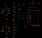
Now i am having some other problem, i am posting my circuit diagram, SPI connections are not shown for simplicity as they are correct because i am able to read internal temperature of ADS1118.

I have to measure the J-Type thermocouple temperature with this, can any one tell me how can i calculate temperature of connected thermocouples, and also how can i sense the open and short condition on the thermocouple ports.

ADS1118 Interfacing with J-Type Thermocouple.png
 

Calculation of thermoelement temperature is discussed detailed in the datasheet, I think.

You circuit has pull-up/-down resistors to detect open TC input (gives high temperature, the usual fail-safe solution for heater control). TC short can't be detected by nature of this sensor.
 
Yes it is given in datasheet page no 29 and 30.

The procedure to actually achieve cold-junction compensation is simple and can be done in several ways. One
way is to interleave readings between the thermocouple inputs and the temperature sensor. That is, acquire one
on-chip temperature result for every thermocouple ADC voltage measured. If the cold junction is in a very stable
environment, more periodic cold junction measurements may be sufficient. These operations yield two results for
every thermocouple measurement and cold junction measurement cycle: the thermocouple voltage V TC and the
on-chip temperature T CJC . In order to account for the cold junction, the temperature sensor within the ADS1118
must first be converted to a voltage proportional to the thermocouple currently being used yielding V CJC . This
conversion is generally accomplished by performing a reverse lookup on the table being used for the
thermocouple voltage to temperature conversion. Then, adding the two voltages yields the thermocouple
compensated voltage (V Actual ), where VCJC + VTC = V Actual . V Actual is then converted to temperature using the
same lookup table as before, yielding T Actual .

Where i can find the look up tables and how to use it for calculation purpose.

With ADS1118 i can calculate, Thermocouple Voltage and then i will calculate Cold Junction Voltage using Look Up Table, then add both to get Actual Voltage, then again use look up table to calculate the themocouple temperature.
 

Where i can find the look up tables and how to use it for calculation purpose.
Your question is also answered in the datasheet:

Thermocouple manufacturers usually supply a lookup table with their thermocouples that offer excellent accuracy for linearization of a specific type of thermocouple. The granularity on these lookup tables is generally very precise (at around 1°C for each lookup value). To save microcontroller memory and development time, an interpolation technique applied to these values can be used. By choosing 16 to 32 equally-spaced values from the manufacturer's lookup tables over a desired temperature range, using a simple linear approximation of intervals between is generally very precise.

In case of doubt, Google helps you with "type j thermocouple conversion table".

I would however make a reservation about the suggested method. Converting cold junction temperature to voltage by reverse table lookup is only necessary if you expect a large range of cold junction temperature and attempt very high precision. For standard applications, it's often sufficient to add a temperature offset after a single lookup.
 
Okay, i got your point, as my ambient temperature will be around 25 deg Celsius.
I am facing another problem, when no thermocouple is connected i am getting 0x7FFF in data register, which is correct, because pull-up resistor and pull down resistor comes into action, and thus giving full scale that's why i am getting full scale reading, but when i connect thermocouple in the thermocouple connector i am getting zero (0).
And after disconnecting that, i am getting 0x7FFF once again.
Any suggestions what i doing wrong.

Configuration register values are as follow:-
Internal Temperature - 0x859B
First Differential Channel - 0x858B
Second Differential Channel - 0xB58B
 

but when i connect thermocouple in the thermocouple connector i am getting zero (0).
Temperature difference between thermocouple tip and connctor < 1 °C?

Why are you setting input voltage range to +/- 2 V? Surely not approriate for thermocouple.
 
Thanks for your suggestion, now i had set the PGA to 111 = FS is ±0.256 V
And put the theromocouple in Hot water taken from coffee machine.
Now i am getting value A5 and that are continuously decreasing wrt time as water is getting cooler wrt time.

How to convert this value into voltage, this is 16-bit adc and what is the reference voltage, can you please tell me the formula to calculate it.

Right now, i had set the PGA to ±0.256 V is it sufficient for J-type Thermocouples.

I am assuming that ±0.256 V PGA means, the highest voltage measured by ADS1118 is 0.256V and lowest is -0.256V.
Am i right, please correct if wrong.
 

Status
Not open for further replies.

Similar threads

Part and Inventory Search

Welcome to EDABoard.com

Sponsor

Back
Top