usx
Member level 2
I'm simulating a 3-layer board (energy is coupled by a 'waveguide' from layer 1 to 3) followed by a coupled line bandpass filter.
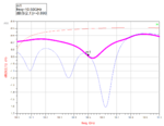
I've simulated coupler and am satisfied with the results. I've also simulated a bandpass filter (albeit, on a single-layer board) and am satisfied with it. I stack them in ADS schematic (coupler and bandpass filter share a ground) and S-parameters add linearly. Next, when I copy and paste those two structures together, I get distorted signal, even though input and output impedances and matched to 50Ω relatively well.

I expected above two circuits give me identical response but it wasn't the case. I don't expect there to be crosstalk between the layers as they are well isolated, so who wouldn't response be identical? Does it have anything to do with how ports are set up in Momentum?

I've simulated coupler and am satisfied with the results. I've also simulated a bandpass filter (albeit, on a single-layer board) and am satisfied with it. I stack them in ADS schematic (coupler and bandpass filter share a ground) and S-parameters add linearly. Next, when I copy and paste those two structures together, I get distorted signal, even though input and output impedances and matched to 50Ω relatively well.
I expected above two circuits give me identical response but it wasn't the case. I don't expect there to be crosstalk between the layers as they are well isolated, so who wouldn't response be identical? Does it have anything to do with how ports are set up in Momentum?