Continue to Site

Welcome to EDAboard.com

Welcome to our site! EDAboard.com is an international Electronics Discussion Forum focused on EDA software, circuits, schematics, books, theory, papers, asic, pld, 8051, DSP, Network, RF, Analog Design, PCB, Service Manuals... and a whole lot more! To participate you need to register. Registration is free. Click here to register now.

[AVR] ADC interfacing ATmega168

Status
Not open for further replies.

yokohama

Member level 3
Member level 3
Joined
Dec 29, 2010
Messages
55
Helped
4
Reputation
8
Reaction score
4
Trophy points
1,288
Location
Algeria
Visit site
Activity points
1,659
Hi everybody,
I would to drive a solenoid with a mosfet and measuring the current by adding a 0.1 Ohm resistor between the source of the mosfet and the GND. (See the schematic below).
When probing this point with a scope I see this signal (see scope capture below). What I would, is cleaning this signal before sending it to the ADC for a correct reading.
I have tried to do that by adding a LC circuit but the result is poor. Can you please suggest me some solutions.
Thank's.
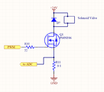
Driver.pngUNIT001.png
 

Need a clarification.... have you checked the resistance of the solenoid coil? Is it comparable to that to 0.1 ohm ?
The spikes are coming because you are switching the solenoid on and off. First check with a constant high signal. Did you check that? What were the results?
 

I have tried to do that by adding a LC circuit but the result is poor.
O.K., sounds like unsuitable filter parameters. The pwm frequency is rather low (220 Hz), I don't believe that a LC filter is a useful option. Instead a higher order RC filter seems appropriate.

You'll calculate the acceptable resisual ripple of your current measurement and calculate filter cut-off frequency and order. Then implement the filter.
 

In my opinion, you can add cap across the current sense resistor (start with lower values in nF). This will over come the spikes in measurement. Then you need to add an amplifier circuit (probably using an opamp) and you can have another RC filer over there. This way the signal getting into the ADC would be cleaner and with better voltage range.
 

@karanmehta93: The resistance of the solenoid is 16 Ohm but it can down to 4 Ohm. You're right the spikes comes from the switching because it is PWM. With a constant hight signal I hav'ent this spikes but the purpose of this driver is to varying the pressure of a hydraulic valve that is why I use PWM. I think this is a mainly used technique to do that.

@Fvm: You are mybe right, the value wasn't correct and well calculated but with this technique I'm worried, if I use a RC filter, it remain nearly nothing in the out of the filter. I mean without the filter I measure with DVM about 0.400 mV when the PWM signal is about 90 to 94%. When I reduce this ratio to 10% this value drop significatly. If I use a RC filter this value drop much more that. I'm thinking about using actif filter (with op amp ) to rise this value and have a better resolution. What do you think ?

- - - Updated - - -

@ravindragudi: I think I'm ahead to that way. Have you more precise description about that opamp configurations ?. Thank's
 

Surely, active filter is preferred. Second order sallen key topology with gain, using an OP with input range including the negative rail.
 

@FvM: This sound good for me. I'll try that and reporting the result here. Thank's.
 

Here is the result:
I've used Sallen-Key Low pass filter.(see the schematic below).
You can see that negative spikes dissapear but the positive still there with less amplitude.
I don't know if these spikes can disturb the reading or not.
Filter.pngUNIT002.png
 

I don't believe that the spikes are actually passing through the filter, they are rather bypassing it due to unsuitable circuit layout, or are simply measurement artefacts caused by the probe ground wire.

In case that the spikes go actually through the filter, which can happen if the OP has low bandwidth and respective high output impedance a higher frequency, extending the circuit with an additional passive low pass to third order would help.

Remember that I suggested a sallen key filter with gain, but don't know if your filter design software supports it.
 

The truth is that I'm trying this on the breadboard. I know this is not the best way to do it but for testing only. Yes the design software I use don't support sallen key with gain, then I'll try another software and see what happend. Thank's FvM.
 

Status
Not open for further replies.

Similar threads

Part and Inventory Search

Welcome to EDABoard.com

Sponsor

Back
Top