Continue to Site

Welcome to EDAboard.com

Welcome to our site! EDAboard.com is an international Electronics Discussion Forum focused on EDA software, circuits, schematics, books, theory, papers, asic, pld, 8051, DSP, Network, RF, Analog Design, PCB, Service Manuals... and a whole lot more! To participate you need to register. Registration is free. Click here to register now.

AD8232 Problem: outputting a noise

Status
Not open for further replies.

Astralist

Newbie level 5
Joined
Oct 29, 2014
Messages
10
Helped
0
Reputation
0
Reaction score
0
Trophy points
1
Activity points
134
Hello,

Have anyone here been using AD8232 chip?
I have some problem with it.

So i've been designing a device for measuring rats ECG using AD8232, but as the board completed, i'm observing these strange phenomenon:

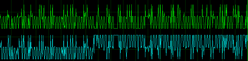
The output is constantly changes, it just like the ad8232 only amplifying a noise (note that these are two ad8232).
Signal swings from 0 to 3.3V (i used REFOUT as reference).
As you can see the swings of the waveform, the green one mostly saturated at 0V while the blue one mostly saturated at 3.3V


The output from IAOUT when the lead is disconnected or when the input is shorted is about 1.5V, is that even normal?
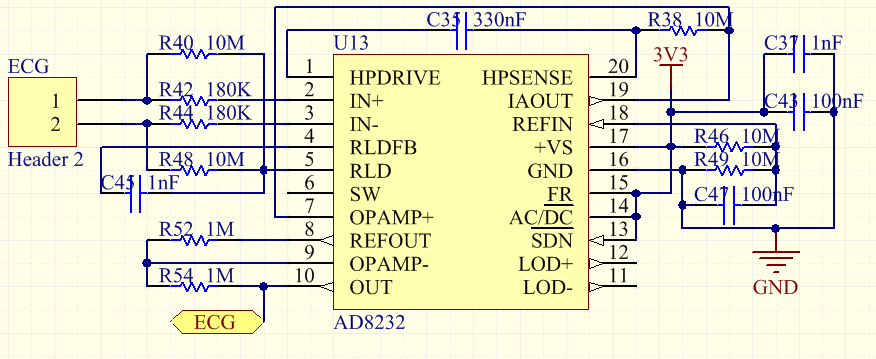
I just follow the sample from the datasheet but with different HPF and with total G=200 referenced at 1.65V from REFOUT, please take a look at the schematic below:


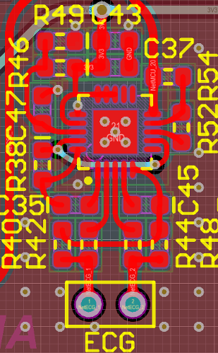
And here is th PCB layout for reference


Please help! :sad:
 
Last edited by a moderator:

Hi,

What do you mean with
note that these are two ad8232

Did you really connect two in parallel?
--> then they fight each other

Klaus
 

That graph is a two AD8232.
What i mean is that each graph represent a single AD8232, ofcourse it it is not connected in parallel, it is read by separate ADC channel.

What you see is output from AD8232 when the input is touched by tip of my finger
 

Hi,

Looking at your scope picture I see two channels, but they seem to be synchronized to each other but one output is inverted somehow. Not exactely.

Therefore I assume you used two AD8232 at the same time...at the same person.

But the circuit is meant to operate solely. Both RLD will fight each other.

The only way I see to operate two circuits at the same time is when both circuits ar galvanically isolated: independent power supplies, non connected scope GND.

Klaus
 

Thanks for reply

Yes it is from different finger but one body.

Actually i'm not using RLD, i just use two probe per device according to the example on datasheet, it should not be a problem then.
 

Hi,

Yes it is from different finger but one body.
You talk about finger, but datasheet talks about arm and leg.

RLD = Right leg drive
RA = right arm
LA = left arm

***********
Actually i'm not using RLD, i just use two probe per device according to the example on datasheet, it should not be a problem then.
For sure you use it. But you don´t bias the inputs by connecting RLD to the right leg, but bias the input with the 10M resistors.

***********
Actually i'm not using RLD, i just use two probe per device according to the example on datasheet, it should not be a problem then.
Where did you find this information? For sure this may cause a problem.

***********
Actually i'm not using RLD, i just use two probe per device according to the example on datasheet, it should not be a problem then.
You talk about Figure 62? Then for sure you have read the folowing couple of words in the datasheet: "Circuit for Heart Rate Measurement Next to Heart"
And you know a finger is not next to heart.

****
--> I recommend to read the datasheet thoroughly

Klaus
 

Status
Not open for further replies.

Similar threads

Part and Inventory Search

Welcome to EDABoard.com

Sponsor

Back
Top