Continue to Site

Welcome to EDAboard.com

Welcome to our site! EDAboard.com is an international Electronics Discussion Forum focused on EDA software, circuits, schematics, books, theory, papers, asic, pld, 8051, DSP, Network, RF, Analog Design, PCB, Service Manuals... and a whole lot more! To participate you need to register. Registration is free. Click here to register now.

Ad8099 cascade .

Status
Not open for further replies.
Hi,

the transfer function of an opamp acts like those of a first order lowpass filter. At the cut-off frequency the magnitude is already attenuated by 3 dB and a phase shift of 45° occures. As the AD8099 has a GBP of 3.9 GHz and your second stage has a gain of 10, your cut-off frequency is 390 MHz. The cut-off frequency of the first stage is 1.95 GHz. Note, the gain-bandwidth-product (GBP) is only applicable for voltage-feedback amplifiers (like the AD8099). As you can see, it depends on the intended/targed frequency. The blue trace (second stage output) results in a phase shift of about ~40° @ 420 MHz.

Please use lables to name your nodes/traces as those lables also appear in the plot and is much easier to identify the related curve. Therefore, make a RMB click on the intended trace, choose "Label Net", choose a name and place the labe on the trace/node. Re-run the simulation, now the vurves jave individual names instead of e.g. n010 within the brackets.

BR
 

Did it! I also understood the GBP (I think). Now I do some tests with the successful stages to have a sufficient output voltage to drive an MMIC.

1.JPG
2.JPG
 

As mentioned by stenzer in post #15, AD8099 has limited slew rate, allowing about 0.3 Vrms output at 500 MHz for a G=10 stage. If you want higher output voltage, you should choose a different OP for the output stage.
 

As mentioned by stenzer in post #15, AD8099 has limited slew rate, allowing about 0.3 Vrms output at 500 MHz for a G=10 stage. If you want higher output voltage, you should choose a different OP for the output stage.

I was looking at it this morning to find another OpAmp that could do well as an intermediate stage and currently I haven't found anything yet. There are actually OpAmp with higher slew rates but they have a limited BW for this purpose. So I was looking for an MMIC that was sensitive enough to be driven by an OpAmp like this.
 

The MMIC amplifiers are generally not DC-coupled and in so far not compying with your initial requirements - if still valid.

Suitable high slew rate OPs can be e.g. found in the Texas Instruments current feedback category, G=10 with 500 MHz bandwidth isn''t offered unfortunately.
 

Hi,

I used the AD8099 several times for frequencies up to 100 MHz. As it provides limited SR and is sensitive to parasitic capacitances (see page 23 in the DS) I used the AD8000 as a replacement. The AD8000 has the same pin out as the AD8099 and does not use the compensation pin C_c, so it is a suitable replacement if the PCB has been realized. Although the AD8000 has only a GBP of 1.5 GHz, this value is not really meaningful as for the AD8099, as the AD8000 is a current-feedback amplifier. Have a look at page 6 figure 7, there you can see the large signal tranfer function for a gain of 10, which results in a cut-off frequency of about 400 MHz. The AD8000 provides a SR of 4100 V/µs.

BR
 

@stenzer

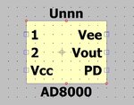
Hi, I had already seen the AD8000 but I stopped because I had problems with the import on LTSpice I had already tried to integrate the AD8000 on one of the circuits where I already had the AD0899 but I had to stop because I had some problems with pins. I wanted to look at it to understand why I didn't have the time. I was hoping to remove an 8099 and put an 8000 on it but as you can see from the screen there is some problem with the pins ,then I looked at the rest!. I don't want to sound presumptuous but these models seem a little badly made to me. Am I wrong? I can also edit the CIR file via a text editor but then does it work? I copy-paste the pin assignments from 8099 file of the 8000 and then I try.
 

Attachments

  • 2.JPG
    2.JPG
    46.5 KB · Views: 88
  • 3.JPG
    3.JPG
    11.6 KB · Views: 84
  • 1.JPG
    1.JPG
    44.1 KB · Views: 85
  • 4.JPG
    4.JPG
    47.1 KB · Views: 92
Last edited:

Hi,

I don't want to sound presumptuous but these models seem a little badly made to me. Am I wrong?

these models are well made by means of modelling the actual behaviour pretty close. I made several measurements with corresponding simulations, and the reaults are in good agreement. How to import these models is an other topic, but LTspice is used by a lot of people and there are several instructions how to import a third order model, you just have to get used to it and do propper web search, heads up!

I copy-paste the pin assignments from 8099 file of the 8000 and then I try.

that wont work, the pins shown in the "header" (.SUBCKT) line have a dedicated name and order. If you have a closer look in the spice file, you will see that these pins (labels/names) are referenced at multiple points. You have to perform the same procedure as for the AD8099 and create a new component. Have a look at the video I linked in post #10 and you linked in #11. For your current simulation you can not replace the AD8099 by your created AD8000 model as it does not has a dedicated feedback pin (although the physical IC has one). As you can see on page one in the datasheet, the feedback pin is directly connected to V_out, so use the output pin to provide the intended feedback.

BR
 

Hi everyone, today I designed the non-inverting circuit for the AD8000. As a test I chose to try with the resistive values to have a G = 2 so I chose RG and RF at 432ohm and inserting a 50ohm resistor in series for RS. I seem to have done everything correctly but the output signal is flat. Maybe it's tired but I don't see any errors. Thank you.


1.JPG


2.JPG


3.JPG


4.JPG
 

Presumedly an error in the model pin order.
--- Updated ---

We can check your design much easier if you post a .zip including the .asc, .plt and imported .lib or .sub files.
 

Hi,

connect the power down (PD) pin to +5 V (V_DD). If I remember correctly, for the AD8000 this pin has to be HIGH (fot the spice model).

BR
 

@klauss @stenzer

Solved connecting PD to VCC!. I see a little phase shift. It's normal?
I attach the zip again because I deleted the previous post.

1.JPG
2.JPG
 

Attachments

  • bit.zip
    3.2 KB · Views: 61

Thanks everyone for the help. I abandon the project because what I want to achieve is not possible. If nothing else, I have a good basis for using LTSpice.
 

@stenzer

Hello, today as curiosity i've done a circuito and simulated. With 100uV source gained to 0.4V with "phase to phase" and 4.2mV at 0.4V up to 100Mhz. If I have not misinterpreted the values I have about 1% of noise. I used a lot of cascaded opamps. It is very far from my initial idea and probably the circuit with appropriate feedback could possibly be improved. How reliable can the simulation be from a real circuit?

1.JPG
2.GIF
 

Hi,

what do you mean with 1 % of noise? What is your noise bandwith? According to your attached plot you have performed a noise analysis up to about 30 kHz. On the other handside you are aiming to utilize a measurement bandwidth up to 100 MHz. I hope you are aware how the measurement bandwidth influences the emerging noise, have a look at [1].

I assume the Spice models are in good agreement with the real world behaviour. Once I performed an noise comparison of the AD8099, where I compared analytical results with measurement results. The measurement results and the analytical ones were pretty close. The Spice model also includes the 1/f noise which is typically not considered in a classical (analytical) noise analysis (I have not included it for my AD8099 analysis). Thus I assume the noise determined by the Spice model is even more accurate.

[1] https://en.wikipedia.org/wiki/Johnson–Nyquist_noise#Noise_voltage_and_power

BR
 

HI,

I assumed that on 4 volts of output having a noise of 4mV seems good to me. If the reasoning is correct. Thanks for the rest.
 

Hi,

are you talking about 4 mVRMS (Root Mean Square) or 4 \[\frac{mV}{\sqrt{Hz} }\]?

BR
 

@stenzer

You actually pointed out to me that they are mV/Hz and my speech falls down.
 

Please also review post #4. I estimated several 100 mV output noise for the slightly higher gain of 11k you assumed four weeks ago. It's mainly caused by white noise above 10 kHz. Low frequency noise has huge density but doesn't contribute so much with 100 MHz total bandwidth.
 
Last edited:
Status
Not open for further replies.

Part and Inventory Search

Welcome to EDABoard.com

Sponsor

Back
Top