Vermes
Advanced Member level 4
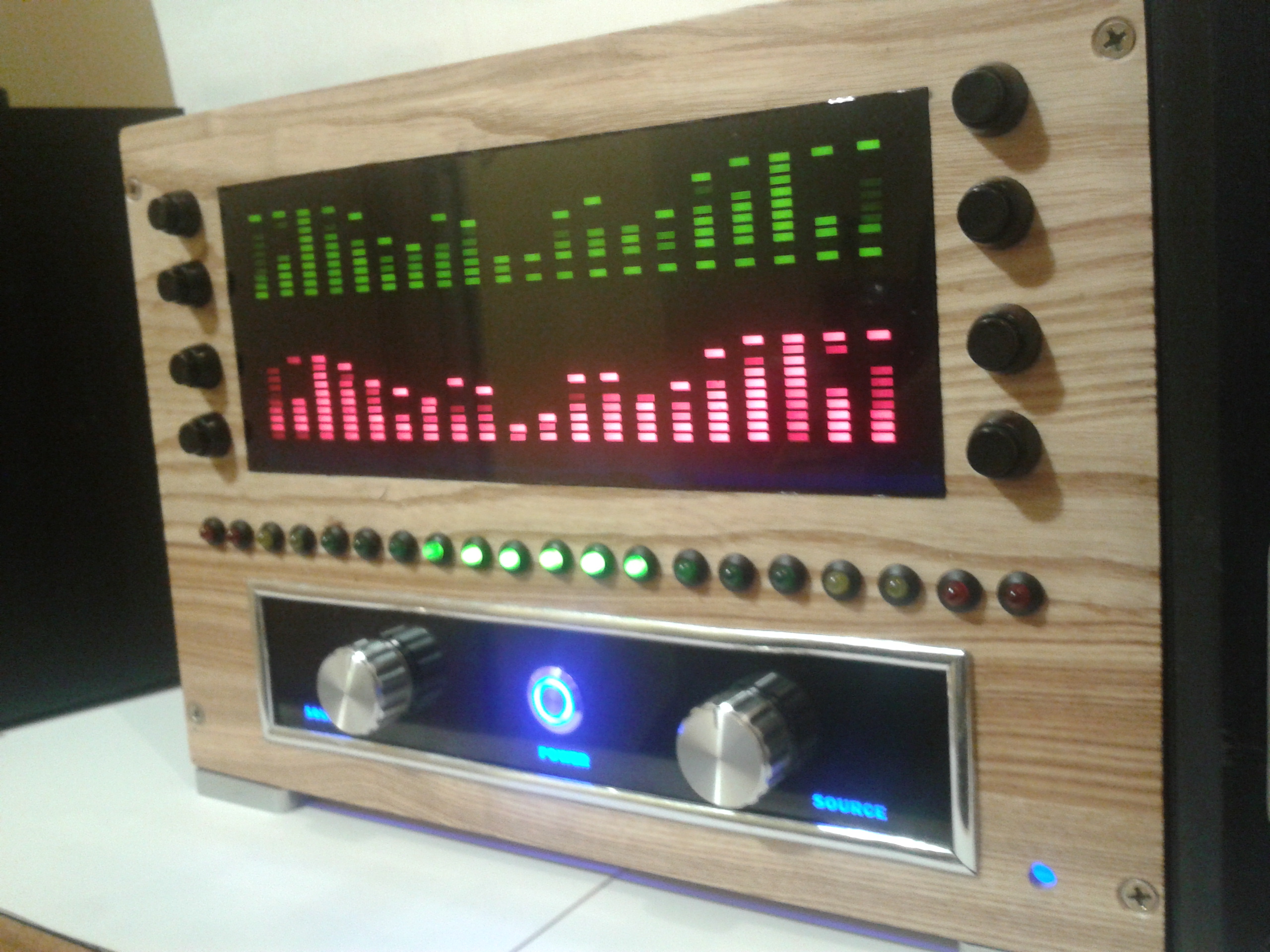
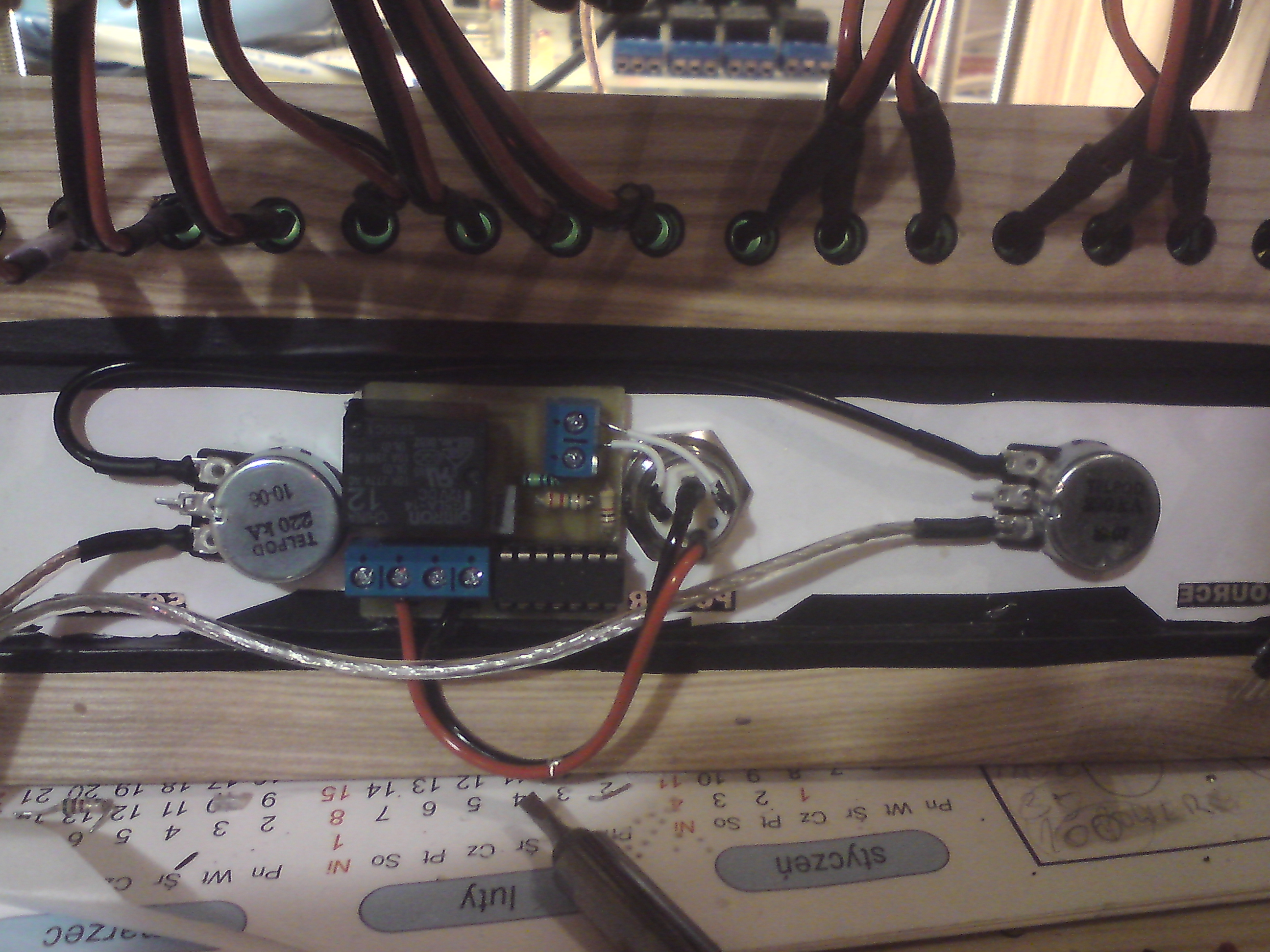
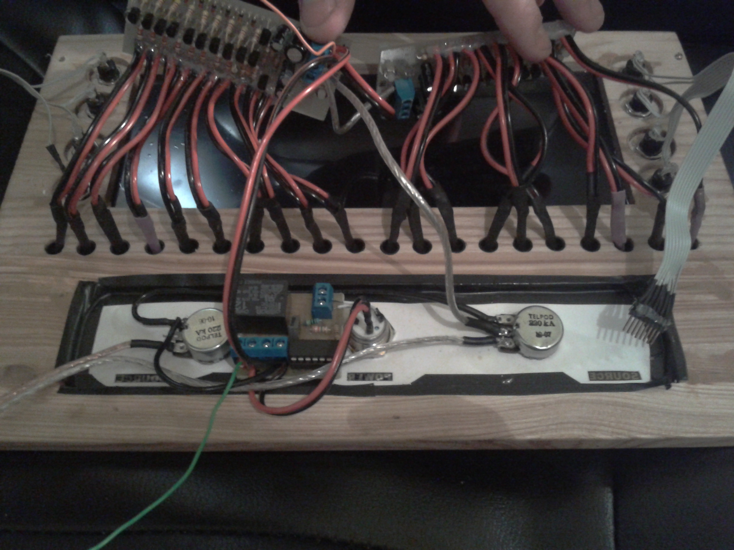
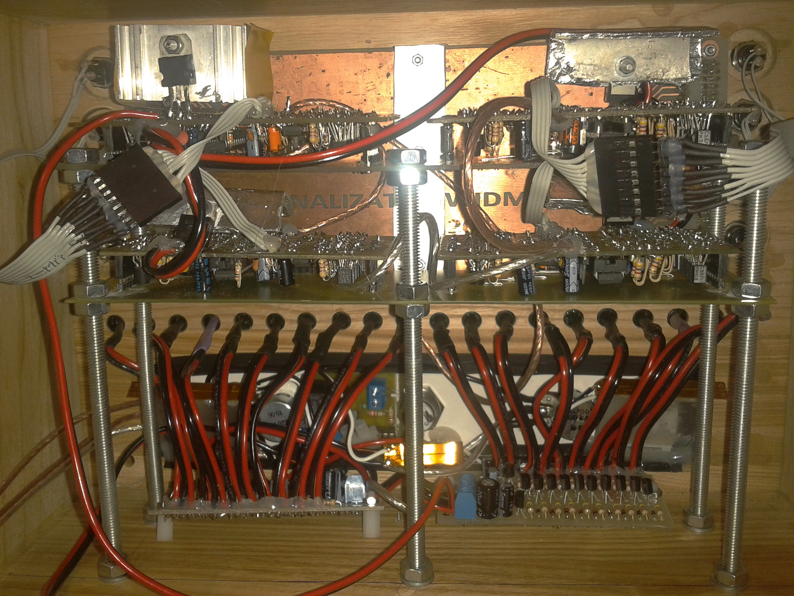
This acoustic spectrum analyzer is based on AVT2864 kit and the level meter NE016. The boards were made in thermal transfer method. Microcontroller used was Atmega8 and the filter used was IIR. 2864 kit includes 10 channels (10 rows each), so there are four such systems applied in this project. When you use monostable switch instead of bistable, you have to design a system which enables and disables the switch using a pulse. The switch is carried out on a chip 40106.
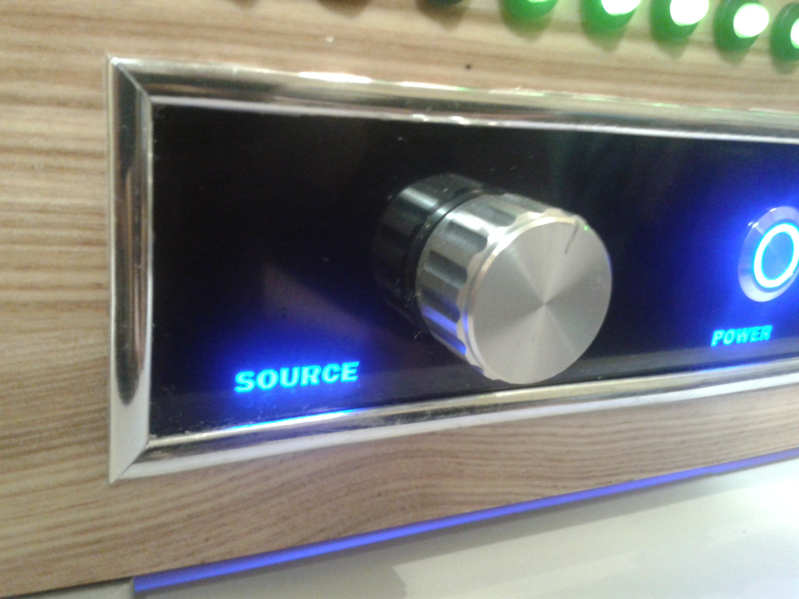
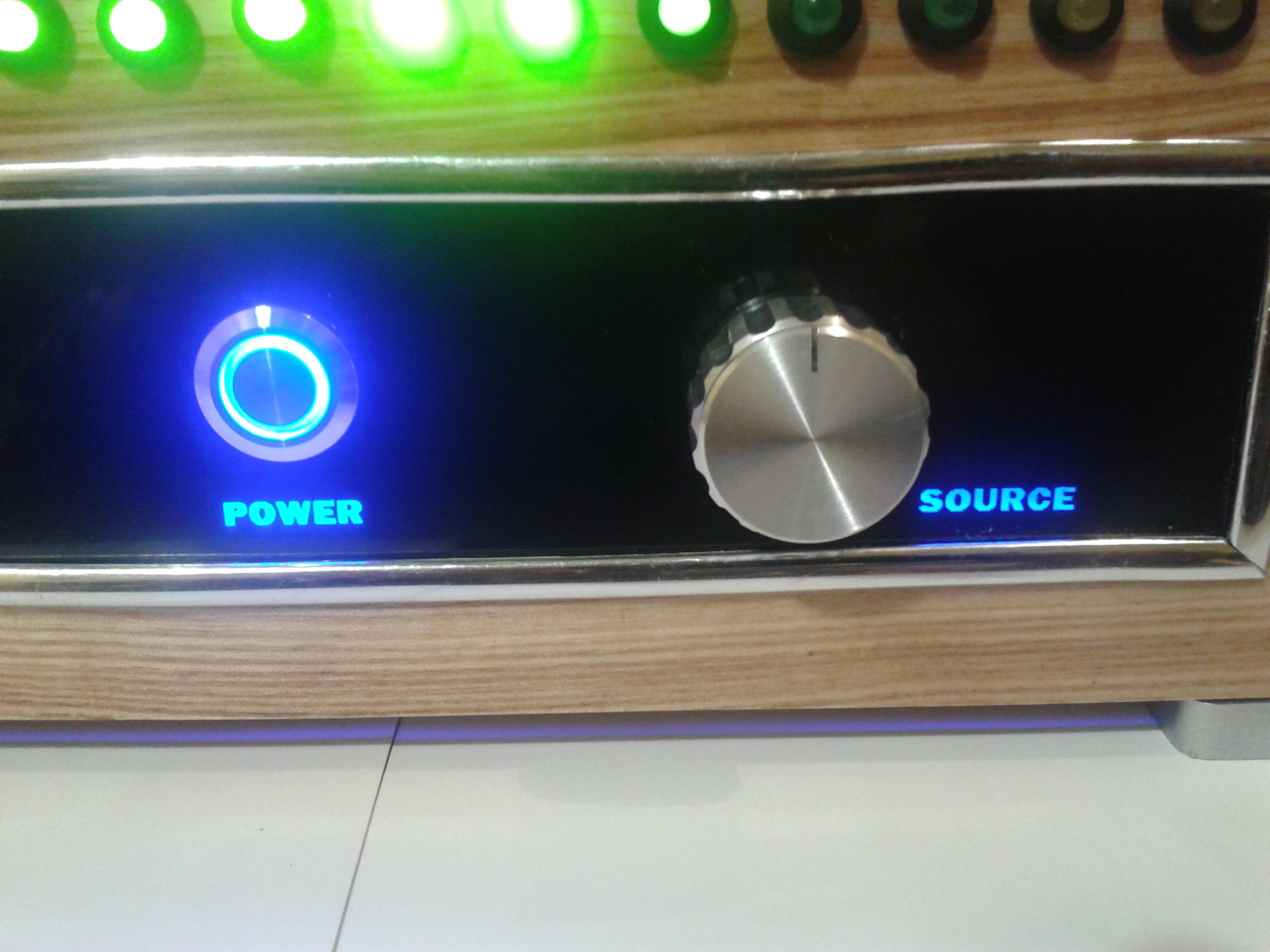
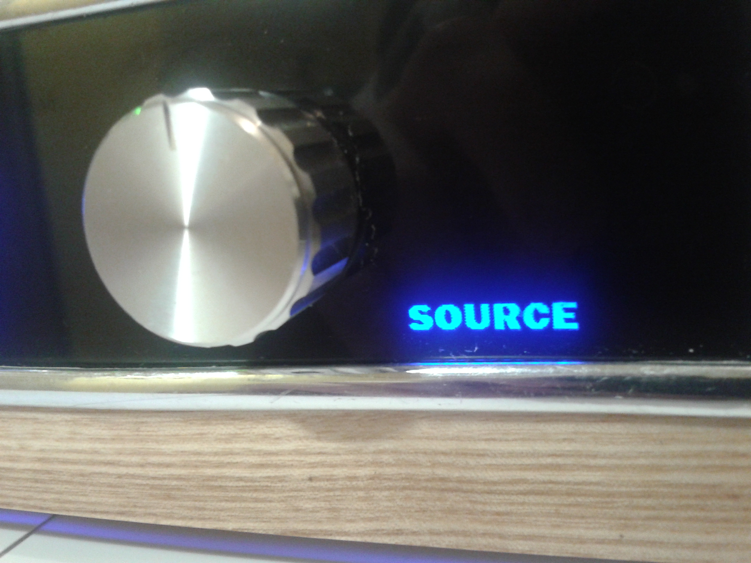
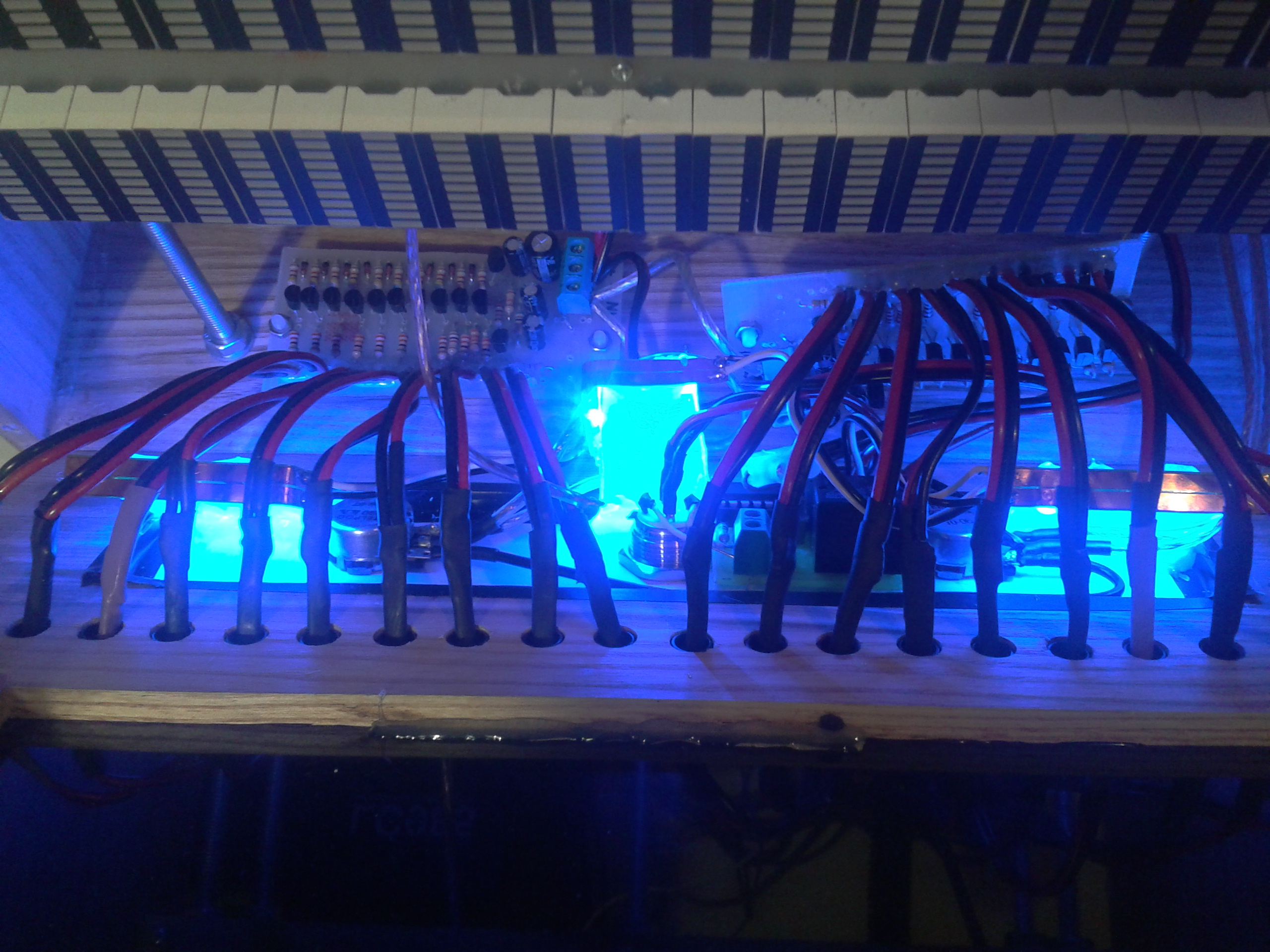
Potentiometers limit the signal coming to the analyzer and the level meter so you can easily tune them while listening to loud music. Backlight is done by printing on a foil and submitting three layers so it can be clear, and the light derived from LED stripe after coming through 5cm plexiglass satisfactorily scattered light and there is no effect of spot illumination.
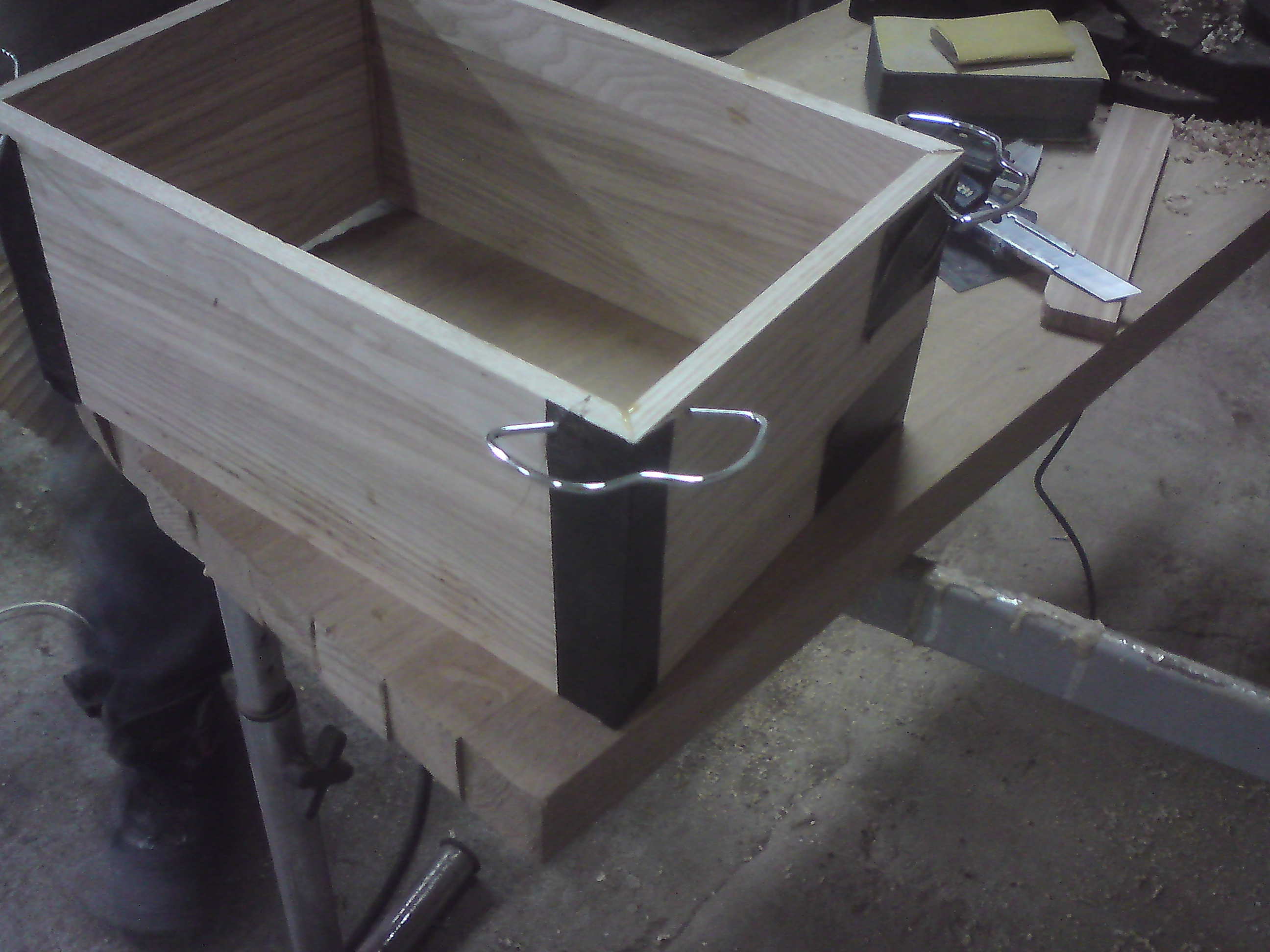
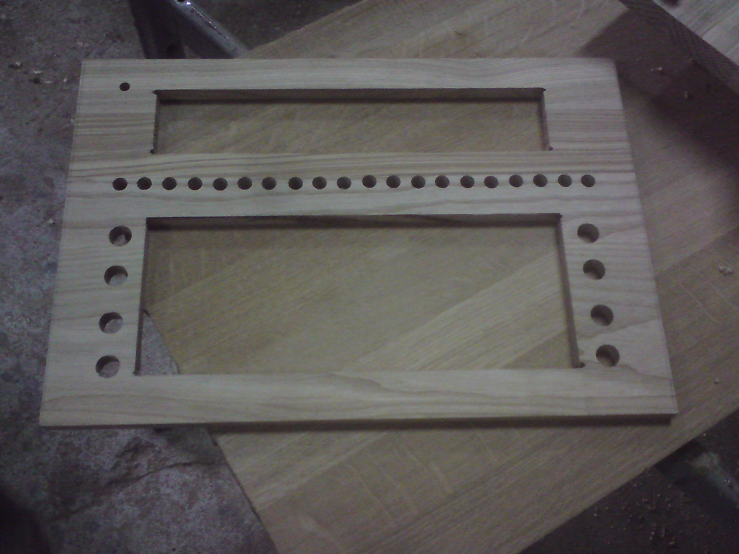
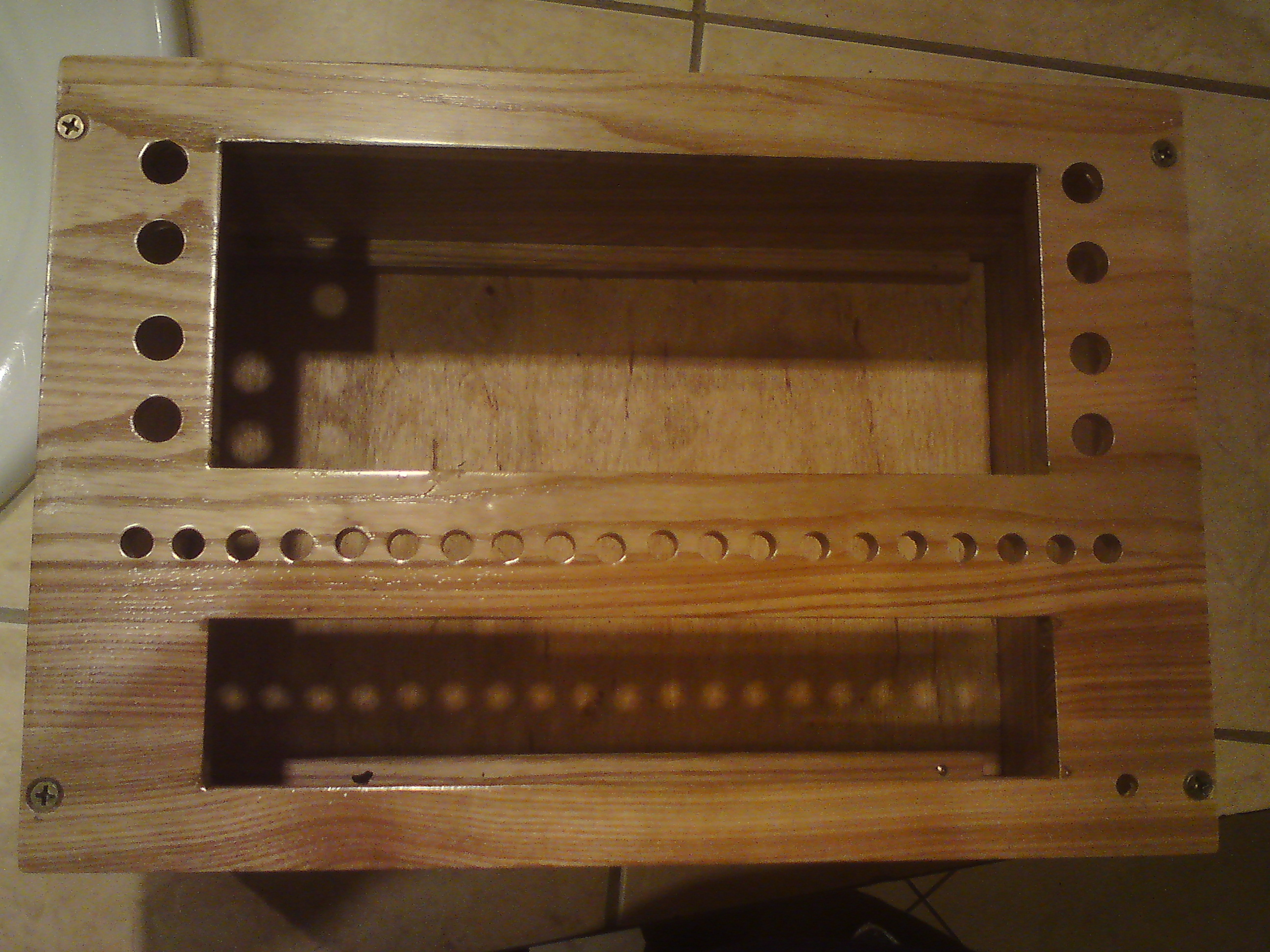
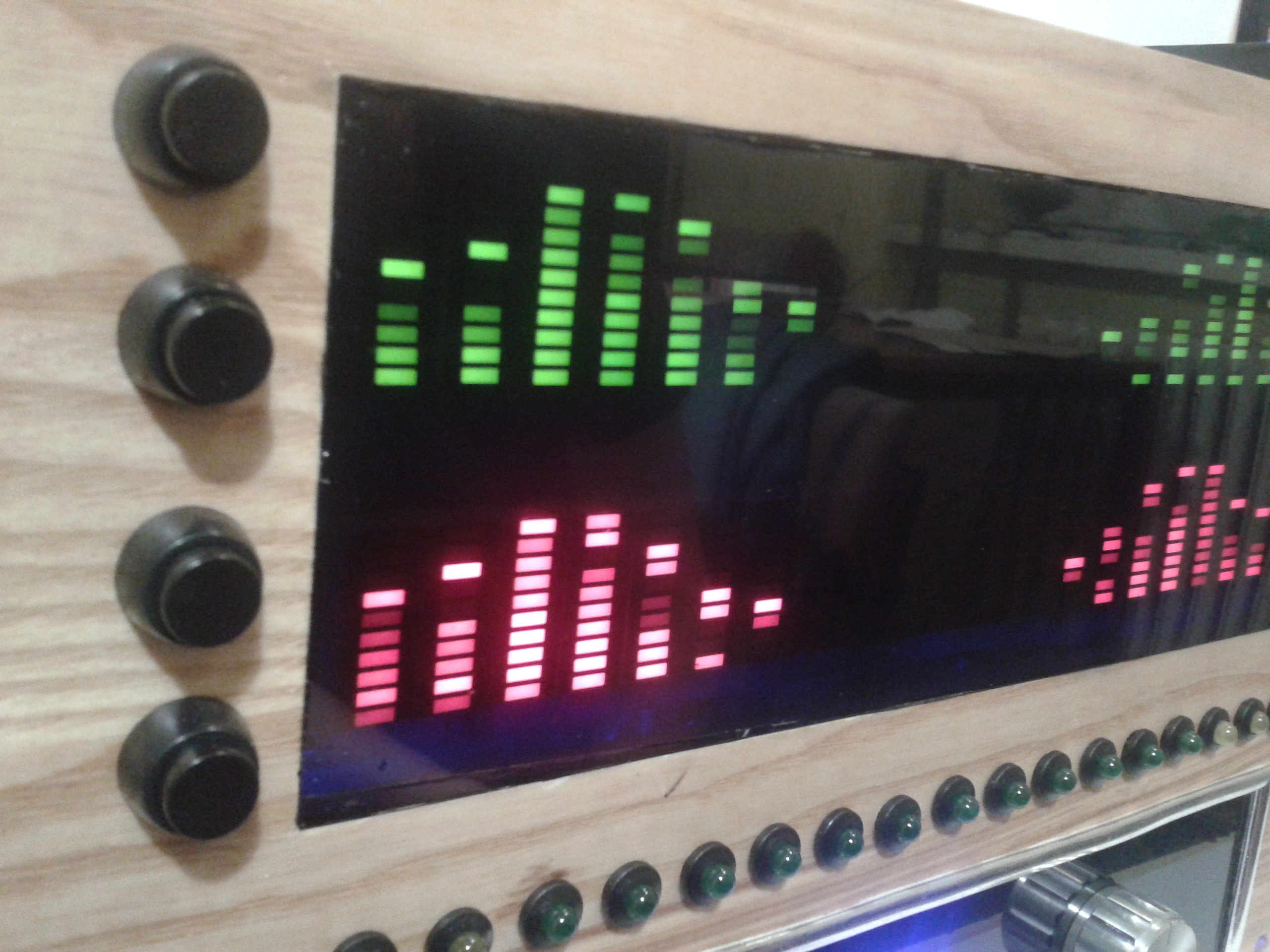
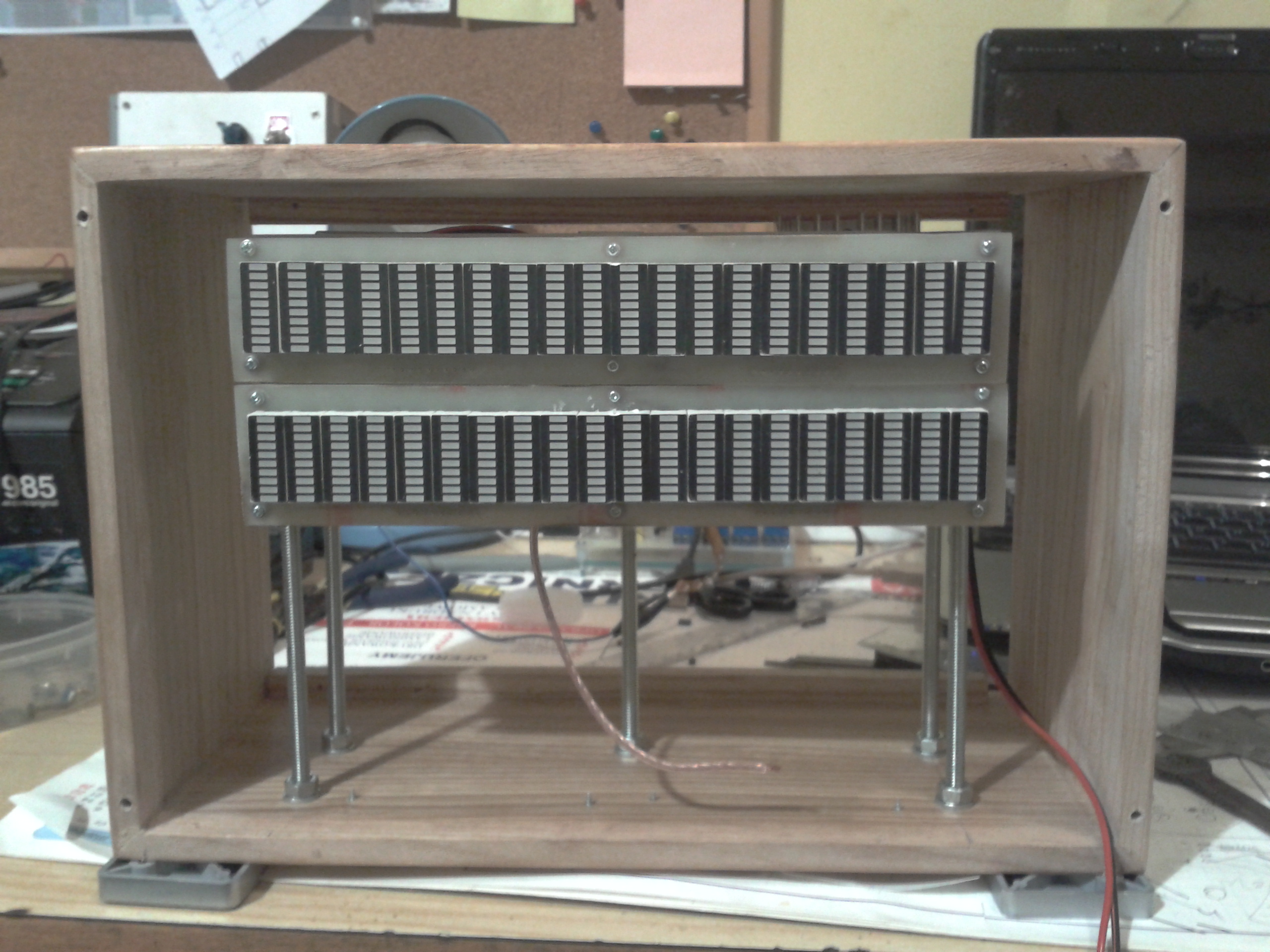
The housing was made of ash wood and lacquered, legs were removed from a wardrobe. Two layers of 40% dimming foil were glued on both regulation panel and operation panel of the analyzer display. If for the analyzer, there are two options: you can glue one layer and gain the effect of lighter green bar graphs or get a completely black area without clearance (with reduction of color intensity). The effect is better for red bar graphs, because the brightness decreases slightly and does not hurt the eyes.
The board of analyzer were mounted on a pin with thread (dia 8). This provides high accuracy of determining the appropriate height and angle of inclination.
The connections were made in a special way so that you can derive separate signals to both the analyzer and the level meter. It is also possible to connect to one common via short circuit of right switch.
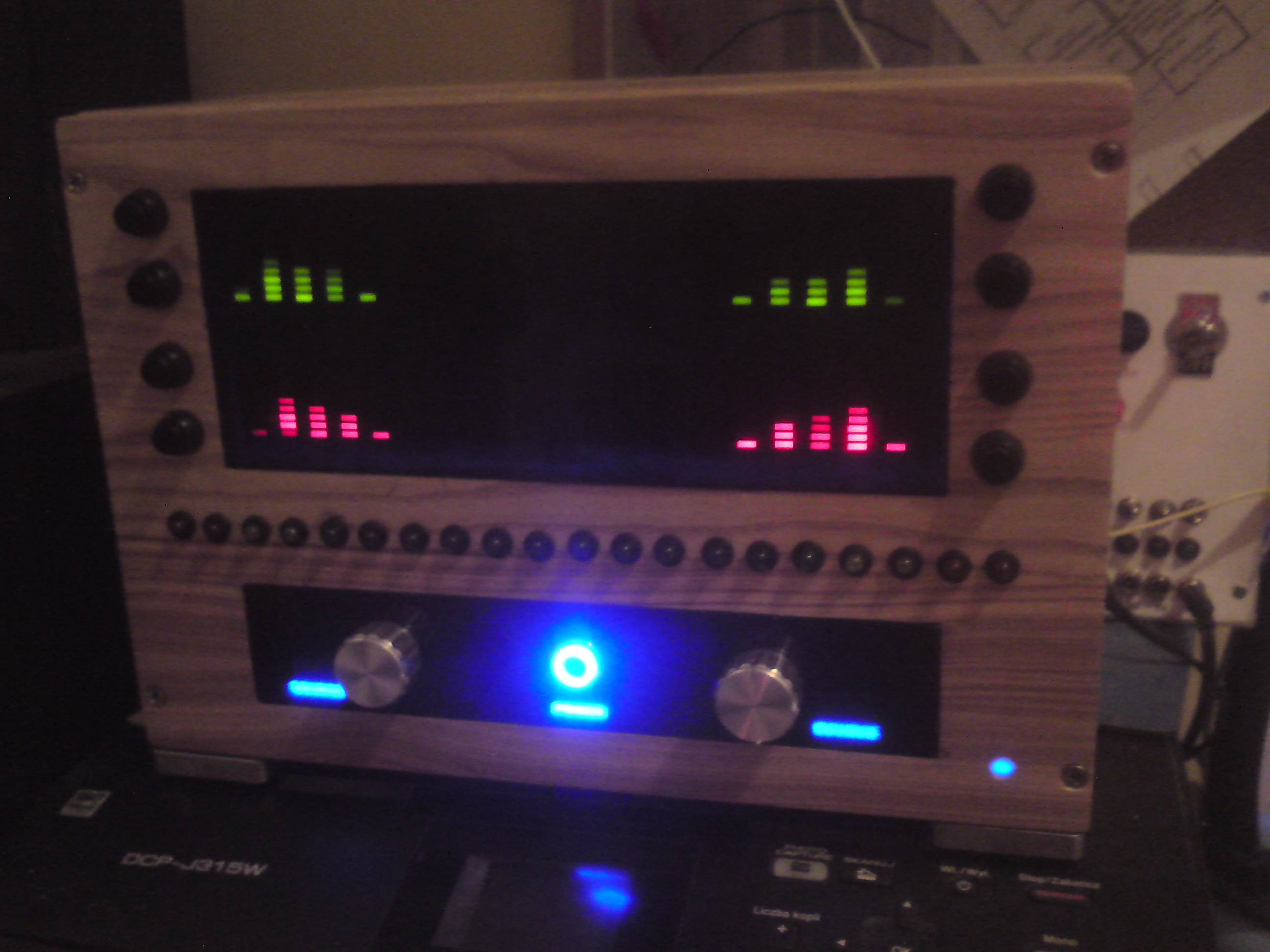
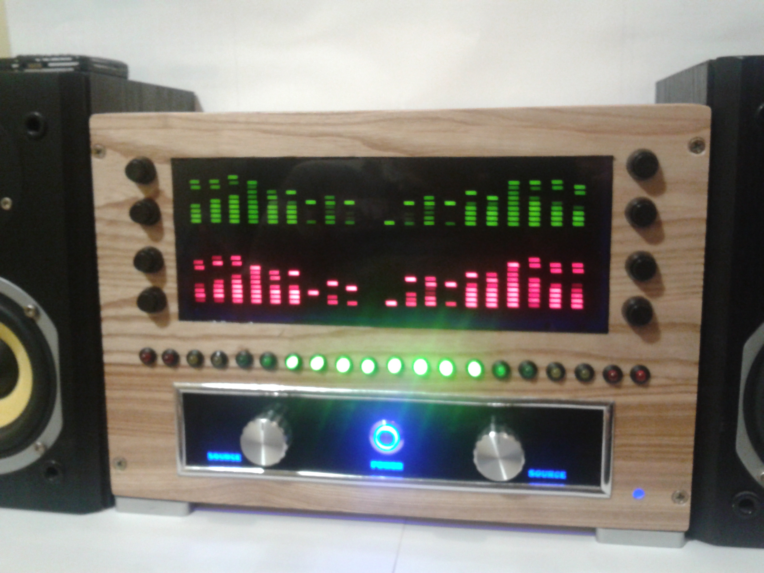
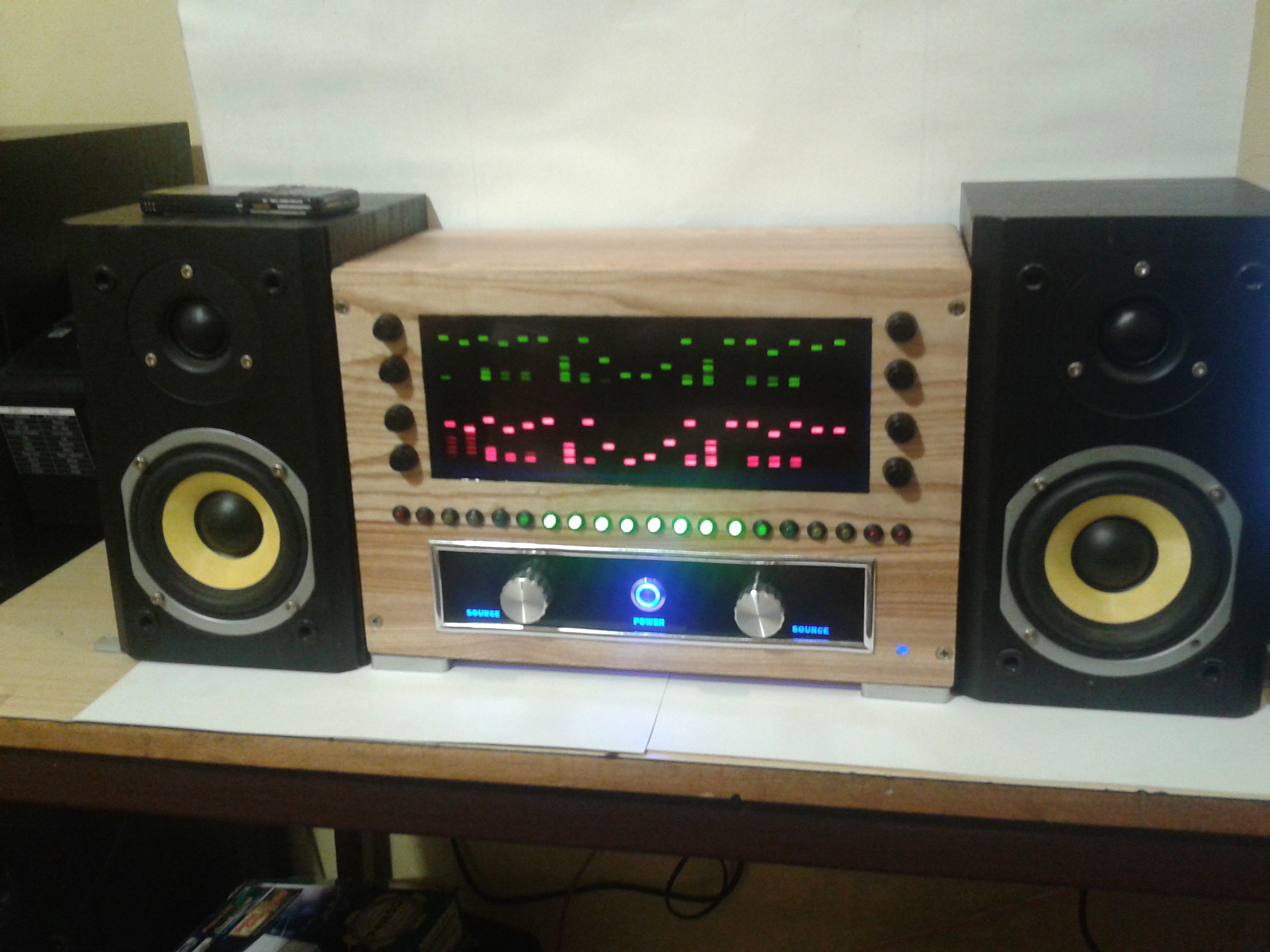
Video shows operation of the system with buttons in the upper part of the panel, which change the display mode.
Link to original thread (useful attachment) – Analizator widma akustycznego i wskaznik wysterowania