Continue to Site

Welcome to EDAboard.com

Welcome to our site! EDAboard.com is an international Electronics Discussion Forum focused on EDA software, circuits, schematics, books, theory, papers, asic, pld, 8051, DSP, Network, RF, Analog Design, PCB, Service Manuals... and a whole lot more! To participate you need to register. Registration is free. Click here to register now.

[SOLVED] Accurate voltage follower

Status
Not open for further replies.

jackmorrison

Newbie level 6
Joined
Jul 11, 2013
Messages
14
Helped
0
Reputation
0
Reaction score
0
Trophy points
1
Activity points
162
I want to increase the current drive of a high-impedance voltage source (function generator or DAC), "LEDV1" input in the schematic, to accurately drive a variable number of parallel LEDs (for illustration, I've shown a pushbutton to optionally connect a second LED). Since the load can change rapidly, I can't use constant-current control. I've set up an NPN BJT voltage follower (common-collector or emitter follower), left side of the schematic below, which works to first order. The PNP input stage is to cancel most of the DC offset - I could remove that for the discussion (remove R1 and Q1, and feed LEDV1 directly into base of Q3), but I've left it in in case it's relevant.

npn_vf.png

The problem is that the output voltage (at Q3 emitter) varies somewhat depending on the number of LEDs connected. For example, for the same input, I get 2.09V with one LED and 1.85V with 32 LEDs. I've tried adding a second NPN (Darlington pair, right circuit with Q4/Q5), and optionally a feedback resistor R7, with little improvement.

Is there a trick to get the output more consistent regardless of load current? I can live with a DC offset, and with a gain that's not exactly 1.0, but I don't want the output to vary depending on the number of LEDs.

Thanks for any suggestions.
 

Do you mean that, in your application, the voltage of the Q1 base may linearly vary to change the LED brightness?
Or it could be low and high only to turn on and off the LEDs.
 
Last edited:

Normally, I'd make the same suggestion as Dominik. But given your existing circuit, I think perhaps you might prefer a discrete solution. So you may want to look into a voltage follower called a "diamond buffer" as well. In its simplest configuration, it's two resistors, two NPN transistors, and two PNP transistors. Gain is close to but not quite one, and there is usually a small bit of offset; but it does a good job of maintaining the voltage regardless of load in my (somewhat limited) experience.

If you're interested and can't find a good schematic, let me know and I'll draw one for you.
 
Do you mean that, in your application, the voltage of the Q1 base may linearly vary to change the LED brightness?

That's right. An on/off switch would be much easier, but not what I need.

- - - Updated - - -

You can use opamp with voltage follower configuration or gate/base follower to drive your load.

That's what I started with, but there aren't many opamps with enough drive, and I was having issues with part failure that I think were from oscillation.
 

Adding an opamp, configured as a unity gain amplifier, to drive Q3, the voltage at Ve will follow the input linear voltage independent of the number of LEDs.
But the maximum LED current and the maximum number of LEDs should be specified first.
 

Adding an opamp, configured as a unity gain amplifier, to drive Q3, the voltage at Ve will follow the input linear voltage independent of the number of LEDs.
,,,,,,,,,,,,,,,,,,,,,,,,,,
As long as the negative op amp feedback point is Q3's emitter.
 

As long as the negative op amp feedback point is Q3's emitter.

You are right but we are not sure yet about the load ;)
And the next question will be about the range of the control input voltage which will be likely determined from the output load; the color of the LEDs and the series resistors
 

you may want to look into a voltage follower called a "diamond buffer" as well. In its simplest configuration, it's two resistors, two NPN transistors, and two PNP transistors.

Interesting, I hadn't seen that before. I'll look into it, thanks.

The diamond buffer circuits I'm finding (e.g. **broken link removed**) are all bipolar. The top half looks an awful lot like the circuit I've started with. If I want a single-supply version, can I use the same arrangement of 4 transistors, but DC-coupled and connected between ground and +V?

- - - Updated - - -

Try replacing Q3 with a Sziklai pair, instead of a Darlington pair.

I'll try it. Thanks for the suggestion and the reference.
 

It seems you prefer not using a general purpose opamp IC as LM358 (8-pin dual-opamp, equivalent to LM324) and you have no final idea about the maximum load though a good design starts from it.
 

we are not sure yet about the load

The drive circuit needs to provide output current up to 640 mA (up to 64 LEDs at 10mA each, or 10 LEDs at 64mA each). Input voltage is somewhat flexible, ideally 0 to 3.3V; useful output (LED Vf) range is 1.5V to 2.5V.

- - - Updated - - -

It seems you prefer not using a general purpose opamp IC

Not necessarily. And just trying to keep up - I appreciate all the quick responses!

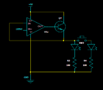
So something like this?

amp_vf.png
 

If you can use an opamp in LM358 or LM324, its linear output limit is about Vcc-2Vd = 5 - 2*0.7 = 3.6V. In other words, the base of Q3 could driven up to 3.5V linearly.
If we assume (from datasheet of ZXTN2501) that the maximum of Vbe is 0.8V @640mA, Ve_max = 3.5-0.8 = 2.7 V

The circuit is this case is simple.
(1) The Q3 base is directly connected to the opamp output.
(2) The Q3 emitter is directly (or via a resistor) connected to the negative input of the opamp.
(3) The Q1 collector (or LEDV1) is directly (or via a resistor) connected to the positive input of the opamp.
(4) Vcc and Vss of the IC could be connected respectively to 5V and ground.

That's all.

Added:
Good work, you already did it.

The second opamp in the IC could be used to map the predefined input control to the useful range of LEDV1.
 
Last edited:
Interesting, I hadn't seen that before.

I only recently became aware of it. Seems to be a basic and useful circuit, yet it also seems relatively obscure; being used almost exclusively by audiophiles as an open-loop output stage, to avoid some type of op-amp distortion that I can't fathom.

If I want a single-supply version, can I use the same arrangement of 4 transistors, but DC-coupled and connected between ground and +V?

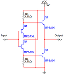
DC-coupled, single supply, and minimal part count:

diamondbuffer.png

2N2222 and 2N2907, or other common complimentary transistors, work fine. It will source or sink current. There may be a better way to do this since only sourcing is required in your case, but I'm far from an expert in analog electronics.
 
The Sziklai pair certainly works better, and the voltage offset is small enough that the PNP input stage can be removed. But it's still not holding output voltage well enough across significant load changes.

I rigged up the opamp with transistor (using an LM308 that was laying around), and that seems to work really well. If I can put a version together with suitable parts that is stable and still has the response time I need, this will be a winner. A dual amp IC is perfect, since I really need two of these drivers per PCB. I'll keep the diamond buffer in mind, but using 3 parts instead of 8 is hard to ignore.

Thanks again for the help, folks. I'll be back when I have more complete results.
 

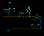
Quick followup: here's what I ended up with. So there's an op amp for accurate feedback-controlled voltage output, a transistor for the heavy lifting, and RC compensation in the loop to squash some high-frequency oscillation I was getting under load. I might need to tweak the RC on the final PCB. I picked out the LM6142 op amp, although it's a standard SO8 footprint so it would be easy to switch that if needed.

ledvf.png

- - - Updated - - -
 
Last edited:

Status
Not open for further replies.

Part and Inventory Search

Welcome to EDABoard.com

Sponsor

Back
Top