Continue to Site

Welcome to EDAboard.com

Welcome to our site! EDAboard.com is an international Electronics Discussion Forum focused on EDA software, circuits, schematics, books, theory, papers, asic, pld, 8051, DSP, Network, RF, Analog Design, PCB, Service Manuals... and a whole lot more! To participate you need to register. Registration is free. Click here to register now.

Ac to dc converter smps

Status
Not open for further replies.

danyasi

Newbie level 5
Joined
Feb 9, 2017
Messages
10
Helped
0
Reputation
0
Reaction score
0
Trophy points
1
Activity points
63
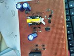
hai i designed a smps which gives 5vdc output and 4amps current .i got 5v dc output .but the problem is when i connect the load output going to drop 3.2vd and load is 1amp.can anyone suggest me what are the reasons for this. the overall circuit is designed on general purpose pcb .
 

Hi,

I assume either:
* bad PCB layout
* saturating transformer

But what do we know without schematic and detailed application informations (exact device specifications)?

Klaus
 

smps sym.png
this is the circuit diagram
 

smps circuit and implementation

this are the schematic diagram .in that output is getting 5v but .when i connected the load it drops to 3.2vdc .please tell me what is the problem .i designed number o transformers but getting same problem
 

Attachments

  • IMG_20170323_170718_HDR.jpg
    IMG_20170323_170718_HDR.jpg
    491.3 KB · Views: 138

hai sir i attached the schematic diagram pls check the circuit
 

Hi,

Still no PCB layout and no device specification of transformer..
And no detailed specification of your application (currents, frequency, operation mode...).

Klaus
 

Undervoltage detection isn't dimensioned for 85V minimal input, review the datasheet. Could be a problem if your input voltage is 120 VAC. 150V zener diode may be inappropriate depending on the transformer windings ratio.
 

sir please send your email id .i will send the data sheet. its urgent to develop this circuit
 

Hi,

This is a forum... for public discusions.
Many other members/guests should gain from the discussion.
Therefore the use of private mail is not usefull.

Read forum rules.

Klaus
 

I will give the complete information
input supply =230vac
output=5vdc
current=4amps
transformer switching frequency =132khz
transformer input =340vdc
used ic TNY290PG.
You can check the tny290pg data sheet.the reference schematic taken from power integration.com

IMG_20170323_170718_HDR.jpg check the hardware part
 

Still lacking transformer specifications (windings ratio, primary inductance).
 

Hi,

In post#1 I assumed:
* bad PCB layout: This is likely, because you obviously don´t use a solid GND plane. I don´t see that capacitors (given in the datasheet) . And I can´t see that you followed the PCB layout recommendations.
* saturating transformer: This is likely, too. because you seem not to know about saturation values of your transformer.

You tell that we should check the datasheet.

Now I have doubts that you followed the datasheet.
Especially sections:
* TinySwitch-4 Layout Considerations
* Key Application Considerations
* Quick Design Checklist.

.. and safety regulations of your region

Klaus
 

Still lacking transformer specifications (windings ratio, primary inductance).

i uploaded the transformer details pls check

- - - Updated - - -

I didn't check .i done the circuit in normal general purpose pcb. now i will do in new pcb board and i will check the result. my doubt is that doing the schematic (hardware) in general purpose pcb will effect ? example : power losses , regulation fail, output drop etc....
 

Attachments

  • t1.png
    t1.png
    122.9 KB · Views: 128
  • t2.png
    t2.png
    105.5 KB · Views: 126
  • t3.png
    t3.png
    88.2 KB · Views: 124

Hi,

I didn't check .i done the circuit in normal general purpose pcb. now i will do in new pcb board and i will check the result. my doubt is that doing the schematic (hardware) in general purpose pcb will effect ? example : power losses , regulation fail, output drop etc....

Only if you are very experienced in low_impedance and precision signal routing you may test such thing with a standard PCB.
In any other case the test gives not the expected results.
Switching power applications are difficult to test, because the PCB layout has great influence on application performance.

Besides performance.... such PCBs can not satsfy the safety requirements. Therefore you risk your own health and maybe the health of others.

Klaus
 

O.K., transformer parameters seems to be in the right ballpark, similar to reference design for this power class.
 

Re: smps circuit and implementation

Well you need to provide schematic design and not just a photo of your breadboard. A common reason for "unexpected" voltage drop, is when the load is trying to pull more power than the supply can give.
 

Re: smps circuit and implementation

It could be because your circuit tries to draw more current than the actual rating.
 

smps output problem ...............

hi
i did the smps circuit in new pcb board .but again getting the same problem output voltage going to drop . and also changed the multiple transformers .but no result. please anyone rectify the problem .pls check my previous posts for circuit. and also check the data sheet of TNY290pg.
 

smps problem..............................

can i use sr5400 schotty rectifier instead of 80SQ045 Schottky barrier rectifier .
 

Status
Not open for further replies.

Similar threads

Part and Inventory Search

Welcome to EDABoard.com

Sponsor

Back
Top