Continue to Site

Welcome to EDAboard.com

Welcome to our site! EDAboard.com is an international Electronics Discussion Forum focused on EDA software, circuits, schematics, books, theory, papers, asic, pld, 8051, DSP, Network, RF, Analog Design, PCB, Service Manuals... and a whole lot more! To participate you need to register. Registration is free. Click here to register now.

AC Sin wave to RCL circuit.

Status
Not open for further replies.

RITESH KAKKAR

Banned
Joined
Jul 6, 2010
Messages
263
Helped
7
Reputation
14
Reaction score
7
Trophy points
1,298
Location
INDIA
Activity points
0
Hello,
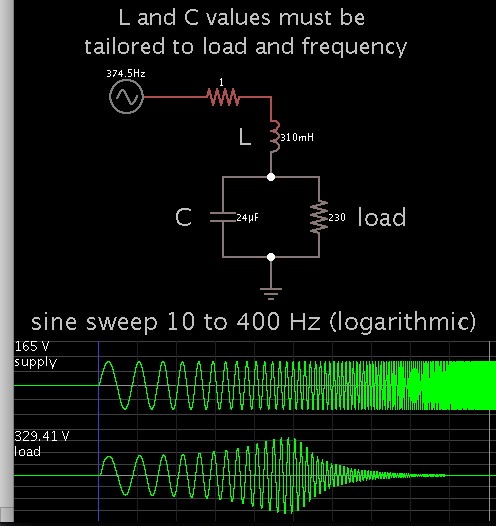
I have notices when we connect the supply to transformer like inductor there is back Voltage/EMF generated which is higher than the applied voltage also depend on the frequency of supply and Capacitor value inductor value and resistance.

why does it happen?
the reason behind it when we remove capacitor it does not happen?
 

Is this a second order LC butterworth filter? The type used on speaker crossovers? It is capable of boosting amplitude at the resonant frequency. Without a load across the L or C, an audio amplifier can ruin its output stage.
 

Hello,
Ok, what does second order mean here?
how to find it frequency where it will bost the signal?
 

Hello,
Ok, what does second order mean here?

Order number is also the number of filter components (generally speaking). That is, components which create a reactive time constant.
When you have only L or C then it is first order.

how to find it frequency where it will bost the signal?

Formula for resonant frequency:

1
----------------
2 * Pi * √LC

You must select an L:C ratio which suits the load. There are online calculators for a woofer or tweeter filter, second order.

I have assumed this simulation is similar to your setup. (I could be wrong.) It is an LCR arrangement which boosts the AC voltage.


The resonant frequency is the point of greatest boost, 50-60 Hz.
 

reactive time constant.
what is this?
and i have listen that to neglect these effect T design is used to have maximum power at load.

ok, in lt spice i got this at resonant freq 75hz
is these circuit used in woofer why?
in which you simulate circuit?

- - - Updated - - -

I dont understand why the ac input signal bost up with both LC in simple i.e. 1st order it does not bost?
 

Attachments

  • aa.jpg
    aa.jpg
    369.2 KB · Views: 156

If you change the simulation duration time to more than 100mS then you'll see that this is just the start of it all, it becomes way larger than what you see after 100mS.

With those components the resonant frequency is 75Hz but I don't get this ether, if you increase the simulation duration too 1000mS then the voltage scale turns into kV:
75Hz.png

I cannot explain this, unless this is just a simulation quirk.
I don't feel this is reasonable at all but then again what do I know.

- - - Updated - - -

Aha I got it, the components we are using can't exist in reality, add a little resistance and the voltage don't freak out like that.
 

I dont understand why the ac input signal bost up with both LC in simple i.e. 1st order it does not bost?

It is not a 1st order. It is a 2nd order circuit.

Why it boosts up ?

There are 2 ways of seeing that.

1) Do the bode plot of the circuit and you will see that at the resonant frequency the gain boosts up to infinity. (which is what you are seeing on your simulation)

2) At the resonant frequency the impedance of the circuit is zero, meaning, you are making a short circuit to the AC power supply !

What happens when a power supply is shorted ? Yes, current goes to infinity (theoretically).

So we have a infinite current passing through a capacitor and a inductor. Each one of them (capacitor and inductor) has an impedance at the frequency you are working. So Voltage in the inductor or capacitor = Current * Impedance = infinity (theoretically)
 

Resonance is a concept that could begin to look as though it can perform miracles. Nikola Tesla made enormous use of it in several of his inventions (example, Tesla coil).

Perhaps you've heard the legend about a small mechanical device, which Tesla took out of his pocket, and attached to a load-bearing part of a building? The device detected a resonant frequency within the structure, then tapped repeatedly at that frequency. Mild vibrations grew in the building, increasing in intensity, until it started to shake. Residents became hysterical, and police were called. The story is too incredible to believe. Nevertheless it illustrates the power of resonant action.
 

1) Do the bode plot of the circuit and you will see that at the resonant frequency the gain boosts up to infinity. (which is what you are seeing on your simulation)

How to draw bode plot?
 

How to draw bode plot?

Once you have the transfer function of the circuit, you can do the Bode plot by hand as it is very common.

However, here is the bode blot of a 2nd circuit. Your case is when ξ=0 (it is not represented, but you can see how it goes as the damping factor decreases) and ωn=2Π*(75 Hz)=ωr (resonant frequency) in this special case.


Tells you what I have said in post #7. The gain (the upper graphic) rises to infinity when you are at the resonant frequency in the case there is no resistor in the circuit.
 

ok the transfer function of this 2nd order equation is:

Vo/Vi = sL / ( sL + 1/sC)

Vo/Vi = sL*Cs / (1+sLCs)

Vo/Vi = s²*L*C / (1+sLCs)
Vo/Vi = s²*90*10^-3*50*10^-6 / (1+s*90*10^-3*s*50*10^-6)

Vo/Vi = ......SOMETHING LIKE THIS.
 

Yes, if you take the inductor as the output. Now you can do the Bode plot. If you take the capacitor as output, you get the same thing except the numerator is 1:
1
G(s)=-------------
LC*s^2+1

A clarification must be made:

In circuit theory, the resonant frequency is the same as natural frequency in control systems i.e. ωn

The resonant frequency is not the natural frequency, ωrn√1-2ξ2

When ξ=0, both are equal.

Let see it better with an example.

Series RLC circuit, with output in the capacitor (because of easier transfer function).

ωn=1/√LC (this is the natural frequency but in circuit theory is called resonant frequency)
ωr=√(2L-R2C)/2L2C (this is the full expresion for the resonant frequency for a RLC circuit)

Why in circuit theory the natural frequency is called the resonant frequency and they never calculate the real resonant frequency ?

Because natural frequency "ωn" is easier to calculate and approaches to the "ωr" (resonant frequency)

Let us use a RLC circuit like the following: R=0.1 Ω, L=90 mH and C= 50 µF

fn=75.02635968 Hz
fr=75.02625548 Hz

And the voltage gain at fr is = 424.26436 V/V or 52.55273 dB

If you want to check this, go ahead and do the Bode plot in LTspice and see that the peak is reached at the resonant frequency "fr" NOT at the natural frequency (in circuit theory called resonant frequency because it is easier to calculate and it is a good aproximation).

PS: I have made the Bode plot in OrCAD and I needed 500 000 points in order to get enough decimals of the peak frequency in order to check calculations.
 
Last edited:

Hello,
What it mean natural frequency mean the system start to oscillate and resonance is when other material frequency match it natural frequency.

how we get this derived ?

The resonant frequency is not the natural frequency, ωr=ωn√1-2ξ2
 

Formulas are derived in books.

I have said that resonant frequency is different than natural frequency, but in circuit theory they only have one, which is resonant frequency.
 

By the way sir, what you do job i mean design or anything else your experience may be useful to many of learners.
 

Status
Not open for further replies.

Similar threads

Part and Inventory Search

Welcome to EDABoard.com

Sponsor

Back
Top