Continue to Site

Welcome to EDAboard.com

Welcome to our site! EDAboard.com is an international Electronics Discussion Forum focused on EDA software, circuits, schematics, books, theory, papers, asic, pld, 8051, DSP, Network, RF, Analog Design, PCB, Service Manuals... and a whole lot more! To participate you need to register. Registration is free. Click here to register now.

AC motor (single phase capacitor/ ceiling fan motor)

Status
Not open for further replies.

atiarali

Newbie level 3
Newbie level 3
Joined
Jan 11, 2014
Messages
4
Helped
0
Reputation
0
Reaction score
0
Trophy points
1
Location
dhaka, bangladesh
www.asuvro.blogspot.com
Activity points
28
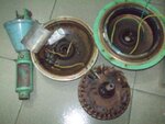
i want to repair my ceiling fan motor. it was brunt when running. i search in books and internet to repair this. but i cant solve the problem.
the fan is 220V AC (50HZ), 1200RPM

it has 2.5uf, 440V capacitor.
any body please help me about the number of turns of the coil. and how to connect the capacitor.

i attached the photo of the fan
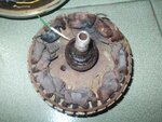
bbbb.jpgnnnnn.jpg
 

Ceiling fans contain unconventional motors. They must run slowly, hence their design is different from typical AC motors.

From your photograph, the windings are numerous and complicated, more so than in a conventional AC motor. This would discourage me from trying to unwind and rewind all those wires.

Like yourself, I have never seen an explanation as to how ceiling fan motors operate. I understand that inefficiency is designed into them, so that they run slowly. I suspect that some windings are oriented so current flows in an opposite direction from other windings, or in different phases. Perhaps different manufacturers achieve this in different ways.

I'm looking at a spot where it appears several wires were burned and separated. Access looks very difficult. If it were just one broken wire, it should be possible to lift away the two ends, and splice them together with a spare length of wire. Instead it appears to be many broken wires, which may be impossible to fix.

If I were determined to save the fan, I would cut away blobs of melted wire, and separate all the ends. I would test each wire with an ohmmeter, for continuity to the power leads. I think only two of them should still be connected to power. The other wires are disconnected turns, unrepairable (unless you want to go to extreme effort to match them up). I could be wrong.

Connect the two wires which show continuity to the power leads. This eliminates several windings, and reduces resistance of the motor. It will draw greater current and generate more heat. This could make it dangerous to operate, and I only suggest it on the chance you have already considered doing this, and know how to be careful about checking for overmuch current draw, and heat generation.
 

It's apparently a two-phase induction motor with 8 pole-pairs. I assume that the two winding strands are running zig-zag around the stator?

It will hardly run at 1200 rpm, rather about 350 with 50 Hz supply.

I agree that it isn't easy to rework at home, but not particularly more complicated than a standard induction motor with stator winding. Counting the number of windings should be a lesser problem if you decide to make it.
 

thanks all to reply me, i want to know how the calculation works , and how to find out the number of winding.... i did a video tutorial "how to make a transformer and ips" i want to make another video tutorial on induction motor.... would anybody say me what is the equation of induction motor?
 

Status
Not open for further replies.

Similar threads

Part and Inventory Search

Welcome to EDABoard.com

Sponsor

Back
Top