Continue to Site

Welcome to EDAboard.com

Welcome to our site! EDAboard.com is an international Electronics Discussion Forum focused on EDA software, circuits, schematics, books, theory, papers, asic, pld, 8051, DSP, Network, RF, Analog Design, PCB, Service Manuals... and a whole lot more! To participate you need to register. Registration is free. Click here to register now.

AC current measurement 1V 10nA 100kHz?

Status
Not open for further replies.

asrock70

Full Member level 4
Joined
Oct 9, 2010
Messages
201
Helped
5
Reputation
10
Reaction score
5
Trophy points
1,298
Activity points
3,252
I try to construct a LCR meter, as I have DDS source that can +-5mV to +-1V, frequency of 100Hz to 1MHz. I would say quite a decent quality signal 2 fixed LPF 7th + active adaptive LPF + three attenuators. As otput amplifier is use AD8021.
Now I deal with current measurements after passing through the measured object.
My first thought was to use an amplifier as the voltage current converter, but I ran into a problem in the upper range. Here I assume limit frequency to 100kHz, the maximum measured impedance 100M.
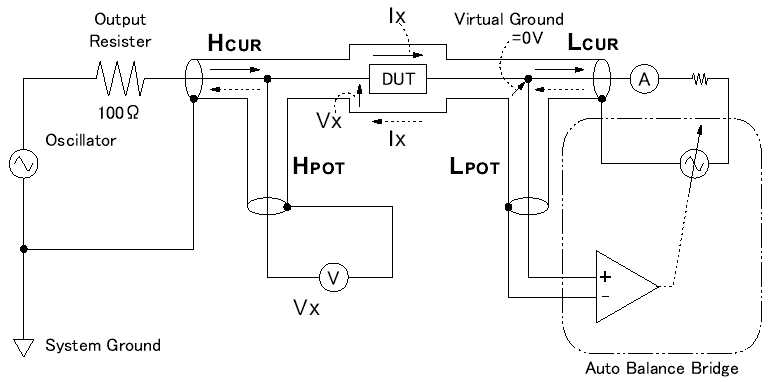
See Figure, V1,U1,R1 is the source signal (in real DDS modul), R2 is DUT, R3, U2 is U to I converter with AD8021.
It works satisfactorily for larger currents, a low impedance measured DUT,
It works satisfactorily for larger currents, a small DUT impedance measured at high impedance begins to have a big impact a small input resistance AD8021 (10M only) and current to or from input AD8021.
Any idea how to solve it?
IV.jpg
 

I am guessing the AD8021 has a BJT differential pair input. This is why there is such a large input current and low input resistance. How about using a different opamp with a FET input. This would provide far higher input impedence
 

May be, the question is what?

I tested, AD865x, but it's still not it would take something better
 

You didn't tell about the actual problems you'll faced in your test. You are only showing a Multisim simulation circuit with standard measurement values, e.g. Vpp and Vrms. Thus I wonder, if your design involves a reasonable signal processing for an LCR meter (phase sensitive synchronous rectification or similar)? The parameter, that limits high impedance measurements the most will be current noise of the input amplifier. In fact, a FET amplifier would be suggested, e.g. AD8065 isn't bad, but I guess you didn't yet approach noise limited sensitivity due to inappropriate signal processing.

P.S.: State-of-the-art digital signal processing for an LCR meter can be found with the Analog impedance measurement chips. Their impedance range is however limited due to the single chip design.
 

You are right, the problem is many.
I take it as a way to become familiar with processing AC signals.
We looked at the diagram Agilent 4284, not that I wanted to achieve his qualities
I started with a signal generator. My solution:
DDS AD9834 with clock 66.66MHz + switching 1MHz LPF 7th or 100kHz 7th or active variable LPF (MAX7407)
+ atteunator 1/2, 1/10, 1/100 + AD8021 as output amplifier and DC offset shifter.
As ADC I think use 16bit 3MSPS ADC AD7621.
They think I thought it would be wrong to use a sampling frequency of exactly 1/4 of the signal from DDS (example DDS 100kHz and ADC 25kHz) and gain direct I and Q
components. Something like a digital IQ modulator.
Maybe it's stupid, but ...
HP says that the current measurement at 1MHz to be use Autobalancing bridge with zeros detector for frequencies <=100kHz is possible using operational amplifier, but it is information from 80 years. May be technology advencing.
 

Attachments

  • AG.pdf
    106.6 KB · Views: 93

I see, that you are already considering digital signal processing. I don't however understand, which problem with the current mesurement you are referring to in your initial post.

The linked 4284 schema is representing a classical analog instrument design, except for the signal generation and succeeding digital acquisistion of analog processed values.

As mentioned before, the concept of the Analog impedance measurement chips can give some ideas for a fully DSP solution:
AD5933 | 1 MSPS, 12 Bit Impedance Converter Network Analyzer | Direct Digital Synthesis ( DDS) & Modulators | RF / IF ICs | Analog Devices
 

AD5933 known. unfortunately unable to measure the impedance below 100Ohm and has some other limitations.
For frequencies up to 100kHz and 12bit accuracy is not the problem using current to voltage converter with integrated amplifier.
For frequencies up to 1MHz, and 16-bit ADC has a problem it can be.

As the "analog" 4284 that "digital" 5933 contain any purely analog part -> current to voltage converter.
Ohm's law is purely analog, and for calculation R we have to measure the U and I.
In the dynamic range 1 miliOhm up to 100 MOhm is need several measuring range with switching in analog part (10 Ohm, 100Ohm, 1kOhm, 10kOhm, 100kOhm)
When you look at the diagram 4284, the majority of boards A3 (Range Resistor) and A2 (modulator) are just purely analog conversion is part of current to voltage converter.
Why are so complicated, HP says (80 years) for frequencies over 100 kHz can not use an integrated amplifier in the Auto balance bridge and must be used
solving with null detector and Phase detector ( as used in 4284)
I recommend for those interested, Agilent Impedance Measurement Handbook
http://cp.literature.agilent.com/litweb/pdf/5950-3000.pdf

The question is, whether today's operational amplifiers already built to current voltage converter in the design that we have outlined in my first post.
If so, what are the appropriate types?
I test AD8651, but it's still not good.
May be ADA4627-1, any Texas Instrument , ....?
 

I suggested to analyze the AD5933 as reference for the implemented digital signal processing, not for the DUT interface.

To say the autobalancing method is used due to bad OP I/V converter performance partly missed the point, I think. In my view, the more important point for high performance impedance measurement is to implement a four-terminal DUT interface, which implies the need for a current source stimulation.

If you change the topology to a more simple two-terminal measurement, voltage source / current sense operation is an option. Returning to your initial post, which restrictions do you experience when using this structure?
 

Maybe I should start this and from that derive more.
Two-terminal measurement if duff.
For measuremet below <10 Ohm or above 10M Ohm is probably need tour terminal with shield.
1.Hc High current terminal as signal source from DDS
2 Hp High potential terminal for measure voltaga on High side DUT
3 Lp Low potential terminal for ....
4 Lc Low current terminal for measure current

Lp terminal is used for balancing brigde so for mesurement voltage between Low side DUT and current meter on Lc terminal
This goes back to the original problem to solve current measurement? :)
 

After reviewing some HP/Agilent LCR instrument manuals, I think the main reason for using the auto balancing concept above 100 kHz measurement frequency is achieving stability for the I/V converter amplifier. I see, that a 100 kHz 4263B is still using a feedback amplifier, despite of the screened four-terminal connection and respective coaxial cable capacitance. The most recent 2MHz 4980 instrument uses auto balancing very similar to 4284. Auto balancing has been also extended to 30 MHz with 4285 and 110 MHz with 4294/4295. The latter uses a very complex circuit beyond the scope of this discussion.

The only competitor instrument I'm aware of is a Quadtech 7600 (there may be others). I only have the user manual, it doesn't tell about the implemented current measurement method.

I think, that a feedback current sense amplifier could be used at 1 or 2 MHz only with restrictions, e.g. screened cables have to be considerably shorter than 1 m (4980 allows even up to 4 m).

Below a block diagram of the 4284/4980 DUT connection. For those, who are not familiar with the auto balancing technique. This is not a feedback amplifier rather than an autotuned (for magnitude and phase) independent source using the same generator as the left side voltage source.

 
Last edited:

May be, the question is what?

I tested, AD865x, but it's still not it would take something better

Check out OPA656 or even OPA657 from TI. You should also model for any stray capacitances on the high-impedance
nodes (output from the 100M to GND), they will have a considerable effect if you'll be using a transimpedance
amplifier.


I'm sorry, but somehow I do not understand the image.
From Output resistor flows over DUT current Ix , but Ix is zero in Virtual Ground 0, because from Autobalance bridge flow opposice current.
What is Ix current with broken line returned over DUT back to system ground over shield of coaxial?
 

but Ix is zero in Virtual Ground 0, because from Autobalance bridge flow opposice current.
Current is supposed to flow in loops. I don't know what you mean with "Ix is zero in virtual ground"? The sum of currents flowing into a node has to be zero (according to KCL), so Ix is continued up to the autobalance source and returning with opposite sign through the cabel screen. No current is flowing to or from the "POT" sense terminals or through the respective cable screen.
 

But then some do not understand how works Autobalance Bridge?
 

But then some do not understand how works Autobalance Bridge?
A detailed description is in the Agilent literature linked in post #7.

In a short, it's a voltage source synchronized with the oscillator connected to the HCUR terminal, with adjustable magnitude and phase. Both are adjusted such, that the virtual ground voltage, measured a LPOT is zeroed.
 

Over the weekend I thought a bit about the problem and and make some measurements.
I wanted to examine the possibility amplifier in the function volt and amper meter.
Signal source, any function gererator Fluke over 100ohm resistor, signal 100Hz, 100kHz and 1MHz sinus 2Vpp
Measurement cable low cost Kelvin clip form china **broken link removed** (coaxila 22AWG cca 1m 4x BMC)
In first step I test possibility amplifier for voltage measurement. i.e. I use AD8021 as noninverting gain=1 RF=75Ohm see datasheet
I use high precision 18bit ADC (National Instrument) and Labview for compare signal (voltage) on 10mOhm, 1 Ohm and 100M Ohm resistor (low side on GND) with output AD8021.
Amplifier with FB resistor have noise 2,8nV/Sqrt(Hz), signal on 10mOhm measured R is 200uV p-p (noise to signal 1:100, nose is cca 3uV on bw. 1MHz))
For scale 1 Ohm - 100 MOhm no problem (from first point of view and simple compare). For resistor < 1Ohm (100m and 10m Ohm test) is starting to show imput offset and output have DC offset, AC signal have good condition.
Conclusion: separately OK, the problem is in the Auto balance bridge I test use OPA656 as I to U converter. Unfortunately, this approach causes problems in approximately low <10 Ohm and High > 10M Ohm . Details, next time here is after midnight
 

Status
Not open for further replies.

Similar threads

Part and Inventory Search

Welcome to EDABoard.com

Sponsor

Back
Top