Continue to Site

Welcome to EDAboard.com

Welcome to our site! EDAboard.com is an international Electronics Discussion Forum focused on EDA software, circuits, schematics, books, theory, papers, asic, pld, 8051, DSP, Network, RF, Analog Design, PCB, Service Manuals... and a whole lot more! To participate you need to register. Registration is free. Click here to register now.

ac-ac converter 230V to 230V

Status
Not open for further replies.

unitt

Member level 1
Joined
Apr 2, 2013
Messages
32
Helped
0
Reputation
0
Reaction score
0
Trophy points
1,286
Activity points
1,518
Hi all
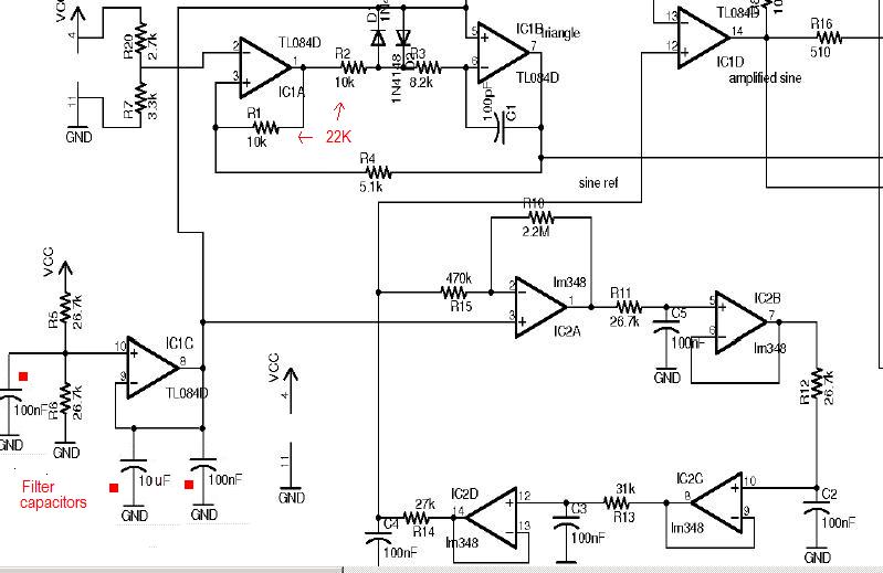
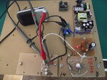
I try to make a converter like the one in the pdf file. I start with
the oscillators. The 50Hz oscillator give no problems, its working on 50Hz.
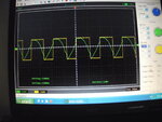
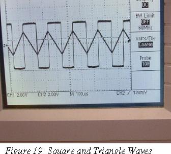
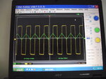
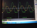
The triangle give a problem, as you can see on the picture, the triangle output, have a big distorion. The opamp I use here is
lme 49740. The distorion is there with low freq, 2.6Khz but too
with 22Khz. I have used 100, 10, 1 nF caps but still distortion.
The square is no problem, so I can't see what is going wrong.
Is here someone who can help me?
Thanks
 

Attachments

  • sinus inverter.pdf
    5.3 MB · Views: 92
  • TriA 2.66Khz.JPG
    TriA 2.66Khz.JPG
    1 MB · Views: 100

You are trying to generate a triangle voltage beyond the OP's linear output voltage range.
 

Hi FvM
I don't know what you mean, beyond the OP's linear voltage range.
I use the lme because the higher slew rate if one will use a higher frequency. stated in the pdf file. I will a frequency between 20-25 Khz.
This higher then the frequency in the pdf file.
 

  • Like
Reactions: unitt

    unitt

    Points: 2
    Helpful Answer Positive Rating
Hi alertlinks
Thank you for your reaction and your answer. The link comes by a real good explanation. So the lme have +10V -10V, if this means by max Vcc then it"s clear why it"s not working, still the square is good.
I use 12V >> 6V on the + input.
It cost some days to get the TL084.
I will do some tryouts what you advice, adjust the resistor and capacitor
 

The waveform you got is probably due to sqarewave ripple on virtual ground (6V). It may be not of low impedence and IN4148 diodes may be causing this modulaion. You can observe this using scope. Add filter capacitors, remove diodes, adjust amplitude by R1,R2 and symmetry of wave by adjusting combination of R7,R20.
 
  • Like
Reactions: unitt

    unitt

    Points: 2
    Helpful Answer Positive Rating
Hi Alertlinks
Have you made this converter?
 
Last edited:

Hi,
You have understanding of this subject, it was indeed the 6 V offset.
I used for both opamps the same 6v, when I use an opamp to create a 6v and supply to the integrator the problem is solved.
And without the 2 diodes.
I use no pcb as you can see, I start with make a drawing and if I
be satisfied I put the parts on the board and connect them.
Its difficult to get a single pcb. I want not to be a pighead, but the opamp here used is a LME.
A lm348 didn't work, very much distorion, and I have no other
quad opamps.
I Know now the Voltage swing with an offset voltage and this
circuit is much more tricky than I thought.
One strange thing, the scoop messure 37.9Khz. but C=10nF,
Rt=2.2K this give a much lower frequency (23Khz)
R=10K and 5.1K
I don't understand this different
 

Attachments

  • lme49740.pdf
    1.1 MB · Views: 71
  • circuit.JPG
    circuit.JPG
    2.4 MB · Views: 87
  • LME.JPG
    LME.JPG
    1.3 MB · Views: 91
  • LM348 distortion.JPG
    LM348 distortion.JPG
    1.2 MB · Views: 87
Last edited:

Status
Not open for further replies.

Similar threads

Part and Inventory Search

Welcome to EDABoard.com

Sponsor

Back
Top