alejo21
Newbie level 2
- Joined
- Aug 21, 2009
- Messages
- 2
- Helped
- 0
- Reputation
- 0
- Reaction score
- 0
- Trophy points
- 1,281
- Location
- Buenos Aires
- Activity points
- 1,303
transistor as a switch
Hello, I'm new to the forum.
I'm having trouble using a transistor as a switch to activate a solenoid electrovalve when an inductive sensor detects metal.
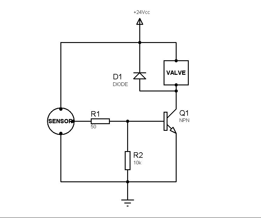
Here's the circuit:
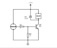
Here are the details.
The sensor is a HT-P12NA PNP Inductive sensor (24V, 200 mA) that has 10V in the output when is sensing metal
The electrovalve has a 24V, 300mA Relay that activates it (it's a pneumatic valve)
I've tried two different transistors: 2N2218 (Vce max=30V, Ic max = 0.8 Amp) and BC639 (Vce max=80V, Ic max = 1A)
The problem is as follows:
With out the electrovalve (using a multimeter as the load) it works just fine, when the sensor is sensing metal, the transistor goes to saturation and I get 24V DC where the valve should be. But, when I put in the valve, and the sensor is on, I only get about 5V, so the relay on the valve never activates.
I tried a lot of Resistor values with no luck. I aldo checked the transistor placement a million times.
Any advice?
Note: As a power supply i'm using an 220V to 24V AC transformer and a bridge rectifier. The DC voltimeter shows a 24 V DC output, but, of course, the supply it's not perfect DC, could that be causing any trouble with the electrovalve internal impedance?
Thanks in advance.
Hello, I'm new to the forum.
I'm having trouble using a transistor as a switch to activate a solenoid electrovalve when an inductive sensor detects metal.
Here's the circuit:
Here are the details.
The sensor is a HT-P12NA PNP Inductive sensor (24V, 200 mA) that has 10V in the output when is sensing metal
The electrovalve has a 24V, 300mA Relay that activates it (it's a pneumatic valve)
I've tried two different transistors: 2N2218 (Vce max=30V, Ic max = 0.8 Amp) and BC639 (Vce max=80V, Ic max = 1A)
The problem is as follows:
With out the electrovalve (using a multimeter as the load) it works just fine, when the sensor is sensing metal, the transistor goes to saturation and I get 24V DC where the valve should be. But, when I put in the valve, and the sensor is on, I only get about 5V, so the relay on the valve never activates.
I tried a lot of Resistor values with no luck. I aldo checked the transistor placement a million times.
Any advice?
Note: As a power supply i'm using an 220V to 24V AC transformer and a bridge rectifier. The DC voltimeter shows a 24 V DC output, but, of course, the supply it's not perfect DC, could that be causing any trouble with the electrovalve internal impedance?
Thanks in advance.