Continue to Site

Welcome to EDAboard.com

Welcome to our site! EDAboard.com is an international Electronics Discussion Forum focused on EDA software, circuits, schematics, books, theory, papers, asic, pld, 8051, DSP, Network, RF, Analog Design, PCB, Service Manuals... and a whole lot more! To participate you need to register. Registration is free. Click here to register now.

About break down voltage of NMOS

Status
Not open for further replies.

tia_design

Advanced Member level 4
Joined
Feb 22, 2005
Messages
113
Helped
4
Reputation
8
Reaction score
1
Trophy points
1,298
Activity points
2,217
snapback voltage

In the process specification, the NMOS breakdown voltage is 7V. Testing case is that NMOS length is 0.6uM, gate, source and substrate are connected to ground, then sweep drain voltage till drain take 1uA current. Process supply is 5V

In my design, I have to take care of protection if op amp's output is accidentally connected to 16V or -6V. If I use NMOS with length of 1.2uM will the breakdown voltage be doubled? Normally how should I do in my design to take care above mentiion 16V and -6V cases. Thanks!
 

nmos breakdown

approximation is vbox=10^9*tox, so if your oxide thickness is 4nm, the breakdown voltage is approximately 4V
 

snapback breakdown

tia_design said:
In the process specification, the NMOS breakdown voltage is 7V.

I think you are referring to snapback voltage, not oxide breakdown voltage?

The snapback voltage is affected by the impact ionization occurring in the drain region. A lightly doped drain lowers the impact ionization and raises the snapback voltage. Gate length has very little effect.
 

snapback voltage gate length

tia_design said:
In my design, I have to take care of protection if op amp's output is accidentally connected to 16V or -6V. If I use NMOS with length of 1.2uM will the breakdown voltage be doubled?
No!
tia_design said:
Normally how should I do in my design to take care above mentioned 16V and -6V cases. Thanks!
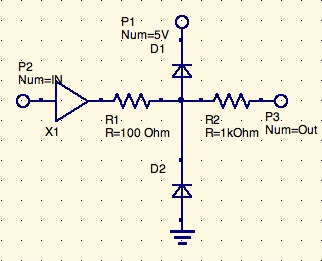
IMHO you can achieve this only by a protection scheme, which normally is used for inputs:
28_1236354754.jpg

Unfortunately, by this you have to sacrifice the low output impedance of the OpAmp.
Probably you can omit R1 (protection diodes directly at the OpAmp output) and decrease R2
- if necessary - as long as R2, D1, D2 and the accidentally connected 16V or -6V sources can stand it.
 

breakdown voltage nmos

use esd protection cells and i/o pads from your foundry. it should be in your pdk
 

Status
Not open for further replies.

Part and Inventory Search

Welcome to EDABoard.com

Sponsor

Back
Top