Continue to Site

Welcome to EDAboard.com

Welcome to our site! EDAboard.com is an international Electronics Discussion Forum focused on EDA software, circuits, schematics, books, theory, papers, asic, pld, 8051, DSP, Network, RF, Analog Design, PCB, Service Manuals... and a whole lot more! To participate you need to register. Registration is free. Click here to register now.

about boost converter

Status
Not open for further replies.

Ahmed Kh

Junior Member level 3
Joined
Apr 1, 2014
Messages
25
Helped
0
Reputation
0
Reaction score
0
Trophy points
1
Activity points
154
hello
please i need help my input around 9v
i am doing the hardware for boost converter
my problem when i put load resister around 22 ohm going be too hot as a heater
if i put around 1k ohm the voltage will be increase too much and also if i remove the resister the voltage around be 50v and the normal output voltage have to be 20
what is the load have to be put on output (also with resister or with remove resister )
my best regards
 

How much output voltage and current you require?

post your present circuit
 

How much output voltage and current you require?

post your present circuit

the hardware as the same of this software
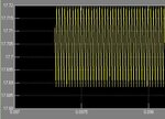
the duty cycle is 50% circuit.JPGresult  at 100 ohm.JPGresult at load 22 ohm.JPG
i design for current 2 a
thanks
 

What is happening is that during the time the FET is on you are charging the magnetic field of the inductor and when the FET is off this energy is discharged into the load via the diode. The capacitor smooths out the voltage pulses.
To get a stabilised output you have to sample the output voltage and feed this back to modify the mark space ratio or frequency, to get the correct voltage. If for simplicity you want it to be unregulated then you have to change the frequency or the size of the L or the amount of current it is taking (changing input voltage), but the voltage will only be correct at one load current.
Frank
 

Try to do with simple switching regulator MC34063.

Refer the datasheet of MC34063.
 

Hi,

You are missing the feedback loop which regulates the line/load in your breadboard implementation. You can google for the control techniques for the boost converter. There are voltage & current control techniques also, PWM & PFM techniques. However, if you don't need the regulation (meaning line & load are constant). Calculate the output voltage & load current. Then place your load resistor according
 

Status
Not open for further replies.

Part and Inventory Search

Welcome to EDABoard.com

Sponsor

Back
Top