naalald
Full Member level 4
class ab site:edaboard.com
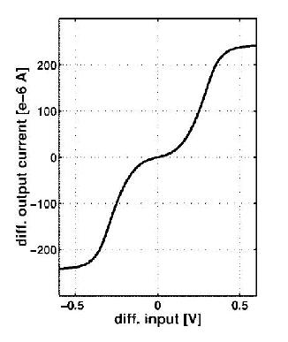
I want to plot the I-V transfer characteristic of a class AB opamp; something like the figure.
How should I do it? It's going to be used in a switched capacitor architecture and the output CMFB of the circuit is switched capacitor. So, should I add two capacitors in the output and plot their current as I sweep the input? How should I sweep the input? By a transient analysis like a pulse wave input or not? This is what I do but the figure I plot is like this (the first curve is the IV characteristic and the second one is the pulse I use as the input):
But the output current just has some peaks and I don't know if it is right. Furthermore it's not the same as the IV characteristic in the first figure.
Any ideas?
Thanks.
I want to plot the I-V transfer characteristic of a class AB opamp; something like the figure.
How should I do it? It's going to be used in a switched capacitor architecture and the output CMFB of the circuit is switched capacitor. So, should I add two capacitors in the output and plot their current as I sweep the input? How should I sweep the input? By a transient analysis like a pulse wave input or not? This is what I do but the figure I plot is like this (the first curve is the IV characteristic and the second one is the pulse I use as the input):
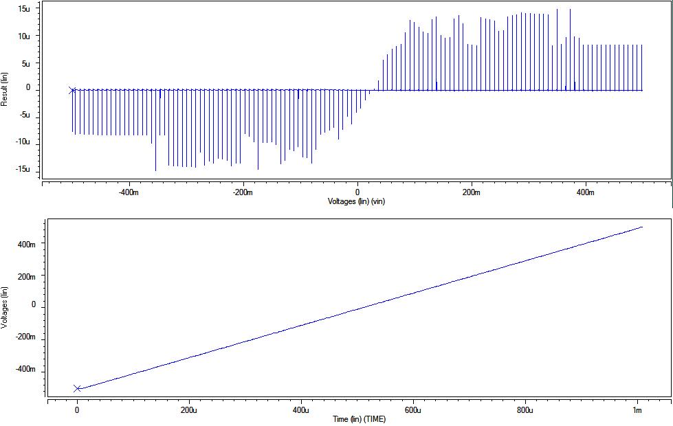
But the output current just has some peaks and I don't know if it is right. Furthermore it's not the same as the IV characteristic in the first figure.
Any ideas?
Thanks.