Continue to Site

Welcome to EDAboard.com

Welcome to our site! EDAboard.com is an international Electronics Discussion Forum focused on EDA software, circuits, schematics, books, theory, papers, asic, pld, 8051, DSP, Network, RF, Analog Design, PCB, Service Manuals... and a whole lot more! To participate you need to register. Registration is free. Click here to register now.

A circuit that can adjust a resistance and probing a voltage node

Status
Not open for further replies.

henry kissinger

Member level 2
Member level 2
Joined
Nov 19, 2021
Messages
44
Helped
0
Reputation
0
Reaction score
0
Trophy points
6
Activity points
442
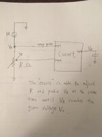
I am trying to design a circuit that has function as below.
There is a current source of 1A.
This circuit is able to adjust resistor R and probe VA at the same time, until VA reaches Vx given.
The goal is get the resistance R.
Any idea is appreciated about how to implement this circuit function.
 

Attachments

  • 281801688_4867095760080293_1934691204824317571_n.jpg
    281801688_4867095760080293_1934691204824317571_n.jpg
    608 KB · Views: 59
Last edited:

KlausST

Super Moderator
Staff member
Advanced Member level 7
Joined
Apr 17, 2014
Messages
23,505
Helped
4,758
Reputation
9,537
Reaction score
5,172
Trophy points
1,393
Activity points
155,888
Hi,

I don't understand of what you really want to achieve.
If you really want to "R" then it needs to be a big adjustable resistor with wiper

Resistor:
* size of a beer bottle
* maybe wire wound
* motor driven wiper

Alternative: build R as an array of resistors (series or parallel wired) that individually can be switched ON/OFF to get the desired value.

Klaus
 

d123

Advanced Member level 5
Joined
Jun 7, 2015
Messages
2,502
Helped
494
Reputation
992
Reaction score
525
Trophy points
1,393
Location
Spain
Activity points
27,128
Looks like a variant of a high-side current source using a Vref, PMOS, current-sensing resistor, and op amp to extrapolate a voltage as a resistance value. And anyway, I'm pretty sure that someone already told you how to do it in the first thread you posted on this topic...

People use a CD4017 as a simple DAC.
 

barry

Advanced Member level 7
Joined
Mar 31, 2005
Messages
6,066
Helped
1,178
Reputation
2,368
Reaction score
1,339
Trophy points
1,393
Location
California, USA
Activity points
32,994
You don't say the range of your resistance, but you may need a resistor(s) the size of a beer keg, never mind a bottle. A 100 ohm resistor will dissipate 100 watts.

And I, too, have no idea what you're trying to accomplish here. You're setting some voltage Vx and then trying to find a resistor that will produce that voltage with 1 amp? Why?
 

betwixt

Super Moderator
Staff member
Advanced Member level 7
Joined
Jul 4, 2009
Messages
15,845
Helped
5,093
Reputation
10,211
Reaction score
4,960
Trophy points
1,393
Location
Aberdyfi, West Wales, UK
Activity points
134,146
I think they are asking for an adjustable constant current sink but it's a strange way to do it and is reliant on the 1A being from a constant current source itself.

Brian.
 

BradtheRad

Super Moderator
Staff member
Advanced Member level 7
Joined
Apr 1, 2011
Messages
14,806
Helped
2,878
Reputation
5,768
Reaction score
2,901
Trophy points
1,393
Location
Minneapolis, Minnesota, USA
Activity points
110,639
Suppose you put the 1A current source in a current mirror, namely the first column? Give it a supply of 1 or 2 volts (therefore at 1 or 2 Watts which is eay to work with)...

Then create a second column for your current mirror...
selecting values so that it derives, say, 1/10 Ampere...
to be applied to your resistor-under-test. It generates a proportional voltage reading. Less watts wasted.

If you wish you can add additional current mirrors and expand your range of useful readings. Say a third which derives 10 mA. Scale your meter reading accordingly.

A fourth current mirror for 1 mA. Scale your meter readings accordingly.
 

FvM

Super Moderator
Staff member
Advanced Member level 7
Joined
Jan 22, 2008
Messages
51,217
Helped
14,653
Reputation
29,584
Reaction score
13,797
Trophy points
1,393
Location
Bochum, Germany
Activity points
292,751
Sorry, but why are you opening a second thread within this forum to discuss the design of one circuitry?
There are even three closely related threads, applying a "variable resistor" in different configurations. You may think that the questions should be discussed separately due to the circuit differences. But the discussion is overlapping in several regards and the possible solutions are also quite similar. If you are able to distinguish the threads now, an Edaboard user reviewing in a month or year will be most likely confused.

That's why we have this forum rule
Select the proper section and don’t post duplicates
Please post your question in the proper forum section, this will help you get replies faster. If your question can fit in more than one category then select the section that seems more appropriate. If you're not sure where to post, ask a moderator first.
Duplicates or cross posting are not allowed, avoid creating multiple threads with similar questions, ask all related questions in one thread.
 

Status
Not open for further replies.

Part and Inventory Search

Welcome to EDABoard.com

Sponsor

Top