Continue to Site

Welcome to EDAboard.com

Welcome to our site! EDAboard.com is an international Electronics Discussion Forum focused on EDA software, circuits, schematics, books, theory, papers, asic, pld, 8051, DSP, Network, RF, Analog Design, PCB, Service Manuals... and a whole lot more! To participate you need to register. Registration is free. Click here to register now.

9v-500v dc-dc converter - - - help with transformer

Status
Not open for further replies.

arivalagan13

Junior Member level 2
Joined
Feb 26, 2013
Messages
22
Helped
0
Reputation
0
Reaction score
0
Trophy points
1,281
Visit site
Activity points
1,477
Hello all,
Am developing a 9V-500V DC-DC converter..
My question is regarding the transformer..
Am in the process of constructing my own transformer as am not able to get one in the market..

I've taken a bobin with E-shaped ferrite core and wounded the bobin with 90turns of 25 Gauge enamel wire as primary..then i surrounded it with an insulating tape..
then again i wounded with 5000 turns of 46Gauge enamel wire as secondary to complete the transformer..

So it should give the 500V DC output (am i correct?.. and of course not a clean DC)
But, to my surprise and disappoinment it is giving only voltage in the millivolts range..

Need support in the construction of this transformer..

Regards
Arivalagan M
 

You didn't mention intended operation frequency, transferred power and core size.

Presumed you have considered winding resistance in your transformer design, winding capacitance probably won't allow to operate it at higher frequencies.

A 9 to 500 V converter might run with a considerable lower turn ratio by utilizing flyback principle. A cascade rectifier can further reduce it if necessary. Finally a small of-the-stock SMPS transformer can work for the design.


Thanks for the response...

Am not sure of the operation frequency but is several KHz...

The secondary power is very less..of the order of milli watts..

I've not calculated winding resistance..will measure it..I don have idea about the capacitance as well...

Kindly suggest me a way of constructing a working transformer..

Finally, I tried with a SMPS transformer..but there are 6 pins on primary side and another 6 pins on other side...

But, am unable to find the primary and secondary terminals..

Next time i'll try to post the pictures of the transformer...

Regards
Arivalagan M
 

Finally, I tried with a SMPS transformer..but there are 6 pins on primary side and another 6 pins on other side...

But, am unable to find the primary and secondary terminals..
People use to design circuits with commercialy available parts based on datasheets and specifications.

Kindly suggest me a way of constructing a working transformer..
Before constructing a transformer, you'll usually calculate the parameters of a suitable transformer that fits your DC/DC converter design. You didn't say anything about the design yet. The assumed 1:100 windings ratio seems rather unusual to me.
 

Questions:

Is this a flyback (sending pulsed DC through your transformer), or are you driving your transformer with AC from a full H-bridge?

What is your operating frequency?

How much current will the load draw at 500V?

What is the expected current coming from your 9V supply? Is it several hundred milliamps?
Does your primary have low enough resistance to carry this?
Does your switching device go to a low enough resistance?

It sounds as though you wound the secondary on top of the primary.
Is this correct? Or are both windings in contact with the core?

- - - Updated - - -

I see progress has been made while I was composing my post.

In case this is a flyback, the orientation of the diode makes a big difference.
During this early stage it might work better if you use a 4-diode bridge, to make sure you are drawing current at the part of the cycle when it is greatest. Because at startup it may be during switch-On, but in normal operation greatest current flows during switch-Off.
 

Well friends..I'll explain the project first..

As I said it is a 9V to 500V dc t0 dc converter...
The 9V battery is used(DURACELL 9V battery which is capable of delivering approximately 400mAh)

So,this current should scaled down appropriately at the secondary..

I've attached a document which has the circuit which am trying to implement..

The document contains two circuits..the lower one is the high voltage generating circuit which am trying to implement...

Briefly,

The input to the transformer is the pulse.. you can see the circuit and the operation will be obvious..

The switching transistor gets the input from relaxation oscillator(Schmitt trigger)..

The duty cycle of Schmitt trigger is controlled to generate the high voltage..

There in the document a voltage doubler network is shown(as the transformer generates only 250V..but i try to generate 500V straight away)...SO i'll not be using doublers..

The feedback loop is designed with an integrator(whose input is the sampling network which samples the raw output and controls the Schmitt trigger duty cycle to check loading)


Am I clear enough?

This is my requirement.. I need to design a transformer for this purpose..

Kindly support..

Regards
Arivalagan M

- - - Updated - - -

And this is a Boost converter I intend to design
 

Attachments

  • PSoCstudy-IGC-report.doc
    86.5 KB · Views: 160

And this is a Boost converter I intend to design

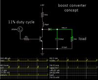
I made a simulation showing it is possible to boost 9V to 500V with one winding:


Since you state the load to be a few mW (I made it 20 mW), you can use a low duty cycle and low current draw from the 9V battery.

This is only theoretical of course, to illustrate the general idea.

I do not know specifically what control circuit will regulate the output voltage of this topology, or whether it needs to work at a lower frequency.
 

I see, a forward converter with voltage doubler output, try running Q1 at 20kHz, with a 45% duty cycle for the on time, this should give you some results, good idea to put a 3W 27V zener across Q1, and a 150pF across the variable resistor (2k2, VR4) to the base - to help with the base drive to Q1.

The two output diodes should be faster types, try replacing each one with 2 x 600V 1A ultra fast diodes in series - this will reduce your losses a lot at 20kHz.

Good luck! and let us know how it all goes...!!!!
 

I made a simulation showing it is possible to boost 9V to 500V with one winding:


Since you state the load to be a few mW (I made it 20 mW), you can use a low duty cycle and low current draw from the 9V battery.

This is only theoretical of course, to illustrate the general idea.

I do not know specifically what control circuit will regulate the output voltage of this topology, or whether it needs to work at a lower frequency.

Thanks for the response friends..
Dear BradtheRad,
Is it possible to suggest some part numbers for transistor and the diode in to work as per your simulation?

Regards
Arivalagan M
 

Thanks for the response friends..
Dear BradtheRad,
Is it possible to suggest some part numbers for transistor and the diode in to work as per your simulation?

Disclaimer: My boost converter simulation is really conceptual. It only works in theory. There's no guarantee my schematic is optimum for your purposes... etc.

The transistor must endure over 500 V at its collector, so you cannot use a general purpose type. I do not know a specific part number to recommend but it should be easy to find one rated for high V.
Normally it will not dissipate a lot of power. It carries 28 mA at a different time than the 500V is present at the node above it.

The diode must withstand 500V reverse. If it were me I would try a 1N4007 just to see if I could get away with it. (That is, if I were operating at a sufficiently low frequency.)
However if you operate at a high frequency then the diode should be a fast recovery type.
 

Status
Not open for further replies.

Similar threads

Part and Inventory Search

Welcome to EDABoard.com

Sponsor

Back
Top