Continue to Site

Welcome to EDAboard.com

Welcome to our site! EDAboard.com is an international Electronics Discussion Forum focused on EDA software, circuits, schematics, books, theory, papers, asic, pld, 8051, DSP, Network, RF, Analog Design, PCB, Service Manuals... and a whole lot more! To participate you need to register. Registration is free. Click here to register now.

8 volts in place of 6 to 7 volts in given diagram

Status
Not open for further replies.

rajaram04

Advanced Member level 3
Joined
Jun 17, 2012
Messages
871
Helped
6
Reputation
12
Reaction score
5
Trophy points
1,298
Location
earth
Visit site
Activity points
7,687
Hello sir
sir in the given circuit diagram below it is mentioned that 6 to 7 volts can be apply but i want to know what if i connect a maximum of 8 volts in place of 7 volts ???

If it is ok then no issue but if it is harmfull for the circuits iam using for 5 volts supply then how to sort out the problem ? what changes we have to make in circuit ??

I am using this kind of circuit specially to drive 3 pin IR sensors . . so please help
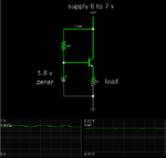
1573909700_1364631739.png
 

What you've got there is a constant current source. Using 8 volts rather than 7 will slightly increase the current into your zener, but other than that, there should be no problem.

- - - Updated - - -

Wait, I'm very wrong.

What you've got is basically a 5.1 volt regulator (the voltage at the emitter will be 5.8-0.7V). And the current through that 330 ohm resistor is NOT 1.2mA as shown. It will be about 3mA (depending on your input voltage). You need to make sure your transistor has enough current gain to supply your load. But, again, 8V shouldn't be a problem.


ohh okk thats great sir

actually i am using a set of 2 batteries each of 4 volts 1 mA

& too there is a set of again same 2 batteriries but with current rating of 2 mA

so should i apply this circuitry freely for IR sensor devices ?
 

what? you've got batteries that can only put out 1mA? there's something wrong here.


oh so sorry my mistake its 1 amp & 2 amp :-x

was too much busy with circuits that time so . . . . .
 

Again, there shouldn't be any problem using 8V. This is not a GREAT regulator, as it's somewhat sensitive to temperature, power supply variation, etc.
 

Again, there shouldn't be any problem using 8V. This is not a GREAT regulator, as it's somewhat sensitive to temperature, power supply variation, etc.


hmm i see so can you tell any other regulator for battery operations ? please help
 

Give me some specifications/requirements: Load current, accuracy, etc. Or, better yet, just go to the websites for Texas Instruments, Linear Tech, Maxim, and they have lots of tools to guide you to the correct part.
 

Give me some specifications/requirements: Load current, accuracy, etc. Or, better yet, just go to the websites for Texas Instruments, Linear Tech, Maxim, and they have lots of tools to guide you to the correct part.


hmm sure sir i ll do but let me explain you what i va my aim actually going on here

I am spreading branches contaning white LED in the room & near about 7 to 8 LEDs minimum are there with its corresponding circuits

But all i want to opearte it with any of remote control unit available so i applied a T flip flop there but this one is made triggered with an IR sensor so i want to make the voltage levels to near about 5 & too regulated one so i obtained this regulator on this forum only . .

thats all about the point i am focussing here cause all the time i don't have the same battery available in market . So . . all these

That's not a specification for a voltage regulator...

1) How much current do you need?
2) What voltage?
3) What package?

For LED's your original circuit would probably be adequate (but you can get a regulator that would reduce your parts count, if that's a requirement).
 

That's not a specification for a voltage regulator...

1) How much current do you need?
2) What voltage?
3) What package?

For LED's your original circuit would probably be adequate (but you can get a regulator that would reduce your parts count, if that's a requirement).


hmm actually all i want regulator for IR reciever unit commercially availabe in market

url.jpg

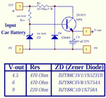
i got some regulators in this forum only but as you explained that it is temprature & voltage effected so i need a regulated 5 volts supply from 6 or 9 or 12 volts battery , current rating maximum 2 Amp
 

This is just a 5V regulator where current is limited by source & temperature rise of transistor from voltage drop * I

View attachment 91817

LM78L05 is better and been around for decades


okk then what about the case when we are usin batteries of 6 or 9 volts ?

how IR reciever will get 5volts ??

is this LM 7805 will help me to operate it ?
 

Last edited:

Status
Not open for further replies.

Part and Inventory Search

Welcome to EDABoard.com

Sponsor

Back
Top