Continue to Site

Welcome to EDAboard.com

Welcome to our site! EDAboard.com is an international Electronics Discussion Forum focused on EDA software, circuits, schematics, books, theory, papers, asic, pld, 8051, DSP, Network, RF, Analog Design, PCB, Service Manuals... and a whole lot more! To participate you need to register. Registration is free. Click here to register now.

7 Segment led display

Status
Not open for further replies.

MKVRAJU

Junior Member level 2
Joined
Jun 14, 2013
Messages
20
Helped
1
Reputation
2
Reaction score
1
Trophy points
3
Activity points
160
hi
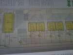
I am using five 7 segment led display common anode(DIS1,DIS2,DIS3,DIS4, DIS5) in my project.i want to control each 7 segment display differently .but in my circuit connection are alternatively connected same pins are e,d,c,dp,b,a,f,g(DIS1,DIS3,DIS5 are same & DIS2,DIS4 are same).
but my question is if i send date to DIS1 display remaining DIS3 and DIS5 also high. connected to DIS1 to DIS5. but i need to send different data to DIS3 and DIS5. can any one help me how to send different data to different 7 segment display.

thank you.
 

in your project which uC use and if not use any uC then post any schematic your circuit diagram ..
 

You have to use multiplexing of displays. Do you want to display a 3 digit data and a 2 digit data on the 3 SSDs and 2 SSDs like 999 on DIS1, DIS3, DIS5 and 99 on DIS2 and DIS4?
 

hi nick703
i am using pic30f5011 micro controller.actually this circuit i taken from electronics for you pulse book.in this circuit they are using AT89C52 uC but i am using pic30f5011
 

Attachments

  • 2013-10-15 10.50.51.jpg
    2013-10-15 10.50.51.jpg
    464.5 KB · Views: 90

hi jayanth

i want display like 12345 but as per circuit how can i controlled DIS1,DIS2,DIS3,DIS4,DIS5. i attached circuit diagram above .in the place of AT89C52 i am using pic30f5011.
 

ok give me a link so i can find this project on efy..
 

hi

can you plese send link or information about MUX.

- - - Updated - - -

hi sorry . i don't have link.i am using hard copy book.august 2013th book

- - - Updated - - -

hi nick703
hi sorry . i don't have link.i am using hard copy book.august 2013th book
 

As I understand your circiut.... you need to make Port P0.2 to P0.6 controlling the Seven Segment Displays ..... So you can use interrupt timer for multiplex them..... Generally way that it is done is running 3.2ms interrupt timer in the micro-controller...

With regards,

Milind
 

Wait for a day I will write a code and post. Mention Clock frequency used. To which PORT of dsPICuC the SSD data lines are connected and transistor bases are connected. The circuit you posted is for a clock which displays time in HH:MM:SS format. For seperator he has used LEDs. Do you want code for clock or just to display numbers? If it is a clock project then for precise time you have to use RTC like DS1307 and then display the data on SSDs. If it is not for clock but to display 6 digit number then the seperator LEDs are not needed. If you want to display number is it floating point or integer value?
 
Last edited:

hi thank you jayanth.
i am using only that circuit but i want display numbers like 12345(DIS1=some integer,DIS2=some integer,DIS3=some integer,DIS4=some integer,DIS5=some integer) and i taken only 5 7-segment display . actually my target is displying ADC value(voltage). i am using 8MHZ crystal frequency.
P2.0 to P2.7 connected to seven segment displays P0.2 to P0.6 are connected base of transistor
 
Last edited:

Files attached. Use 5 2N2222A transistors and 5 NOT gates to enable/disable the SSDs. SSD data lines need current limiting resistors. NOT gates between uC pins and Transistors base.


Attachments

  • dsPIC33FJ32MC204 5SSD.rar
    147.2 KB · Views: 56
  • dsPIC30F5011 8 MHz Ext Clock.rar
    1.6 KB · Views: 57
Last edited:

hi jayanth

your code not open.i think its output file.
 

Jayanth , thanks for prompt reply! But Im not able use you HEX file !
But my intention was to display my adc values which look like 230.66. So in the case I have been trying with 5 seven segment displays.
I was clear with reading my adc values with the processor I am using where I place the read value on to a UART for display.
Now I have taken pins B0 to B8 and gave connection to all 5 display(7 segment) parallely as used in the circuit I mentioned therefore.
From the above discussions I can get that I have to use Multiplexer, but where and how shall i add it ? But to my knowledge i understood he mentions transistors to control segment displays individually. is this and the multiplexer mentioned are the same , or else a circuit to be added ? If so let me know about how he controls the segment display using transistors , and how if a multiplexer added ?
 

Sorry I can't help you. I had asked whether you want to display floating point numbers or integers. You said integers. I don't have time to write code to display floating point.

Databus connected to a,b,c,d,e,f,g,dp pins of SSDs are the multiplexed lines. CA/CC pins are connected to transistors for enabling/disabling displays. If transistors are not used and all SSDs are enabled at the same time then all SSDs will display the same data.

You place data of first digit and then turn ON the 1st SSD for a small time and then turn it OFF, then place data of 2nd SSD on the multiplexed databus and turn ON 2nd SSD for a small time and then turn OFF. The process repeats for all the 5 SSDs. If you want to display floating point number then dp pin has to be turned ON and proper SSD which should display the dp has to be turned ON. SSD value will be ORed with dp value.
 

ok jayanath,
I have done the same with a simpler code. I have done ligthing up individually and now each segment is working.
But then I tried to high all seven segment at once i have errors in getting high all at once and when I gave a little delay in between and given high to all seven segments and it works good.
Can there be any reason why such delays to be given ?

Code:
TRISD=0b000000;
TRISB=0b00000000; //seven segment display confg as a output

PORTDbits.RD5=1; // 1st display transistor connection
delay();
delay();
PORTDbits.RD6=1; // 2nd display transistor connection
delay();
delay();
PORTDbits.RD1=1; // 3rd display transistor connection
delay();
delay();
PORTDbits.RD2=1; // 4th display transistor connection
delay();
delay();

PORTDbits.RD3=1; // 5th display transistor connection
delay();
delay();
PORTB=0b00000000;

while(1);
 

yes this code only make output port bit is high but not driving any 7segment led put more code to know what happening. ? and yes only lighting high but not display any char. so make sure what are u doing with this code??
 

Status
Not open for further replies.

Part and Inventory Search

Welcome to EDABoard.com

Sponsor

Back
Top