Continue to Site

Welcome to EDAboard.com

Welcome to our site! EDAboard.com is an international Electronics Discussion Forum focused on EDA software, circuits, schematics, books, theory, papers, asic, pld, 8051, DSP, Network, RF, Analog Design, PCB, Service Manuals... and a whole lot more! To participate you need to register. Registration is free. Click here to register now.

7.4 to 4.2V stepdown converter

Status
Not open for further replies.

kasamiko

Full Member level 3
Joined
May 23, 2004
Messages
154
Helped
16
Reputation
32
Reaction score
18
Trophy points
1,298
Location
Philippines
Activity points
1,121
Hi,

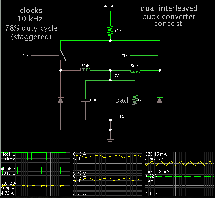
I'm looking for any applicable circuit to stepdown a 7.4 volts source to 4.2 volts with at least 10 amperes continuous current..SMD design is an added bonus..

I was looking at LTM4641 but any suggestions will b e appreciated..
 

A buck converter would be an efficient step-down method.

Consider using a dual interleaved buck converter. You can use two coils rated for 6 or 7A, rather than one coil rated at 12 or 13 A. It would also put less stress on your smoothing capacitor(s), and your power supply.


The above schematic is a bare concept. You would need a control IC which is designed to operate twin converters.
 

It looks good, thank you BradtheRad.
Say, why do we need those inductances? Are this the 'coils' you refered to when you mentioned current stress (of 6A or 7A)?

Also, the duty cycles of the two clocks are both on (logic high) for a certain time. Is this intentional or even important for the converter to work? The hint of 78% duty cycle implies that it has to overlap, not?


Isn't it possible to step a voltage down by PWMing a switch? Always thought that would result in a lower (average) voltage. Or is it important to have a regulated (voltage) output? Think in general it isn't possible to drive a e.g. 5V device by PWMing a 10V supply using duty cycle of 50%? The peaks would kill it, won't they?
 

I just looked at the datasheet of the LTM4641 which you are considering.

Now I see it is a buck converter on a chip. It contains the coil internally (according to the diagram at the website).

https://www.linear.com/product/LTM4641

It should do the job for you, from the description.
 

Isn't it possible to step a voltage down by PWMing a switch? Always thought that would result in a lower (average) voltage. Or is it important to have a regulated (voltage) output? Think in general it isn't possible to drive a e.g. 5V device by PWMing a 10V supply using duty cycle of 50%? The peaks would kill it, won't they?

Yes, this is possible and you could obtain 4.2V this way.
However it is no more efficient than using resistive drop.
Very large amounts of current flow during switch-On time.

I too once thought it ought to be a workable method. Make the smoothing capacitor large enough, and adjust the duty cycle until you get the desired output V.

It does not gain you anything, as it turns out. When pulsing the capacitor, it tends to charge immediately to the supply V, except that there is some amount of parasitic resistance in the loop. (This includes the supply, the switching device, the wiring, etc.). This resistance wastes power as heat.


Notice the large amounts of current that flow during switch-On.
Also the large wattage wasted during switch-On.
 
  • Like
Reactions: JanIan

    JanIan

    Points: 2
    Helpful Answer Positive Rating
Status
Not open for further replies.

Similar threads

Part and Inventory Search

Welcome to EDABoard.com

Sponsor

Back
Top