Continue to Site

Welcome to EDAboard.com

Welcome to our site! EDAboard.com is an international Electronics Discussion Forum focused on EDA software, circuits, schematics, books, theory, papers, asic, pld, 8051, DSP, Network, RF, Analog Design, PCB, Service Manuals... and a whole lot more! To participate you need to register. Registration is free. Click here to register now.

6kVA autotransformer upstream of bidirectional grid tied inverter?

Status
Not open for further replies.

cupoftea

Advanced Member level 5
Joined
Jun 13, 2021
Messages
2,611
Helped
54
Reputation
108
Reaction score
115
Trophy points
63
Activity points
13,687
Hi,

I have just seen a grid tied inverter for connecting a battery to the 240VAC UK mains. Its bidirectional. Its 5.5kWh rated. The mains comes to it via an autotransformer, which knocks the mains down by just 15-20V or so. The reason for the autotransformer said to be because the GTI needs protection should the mains go too high.

This autotransformer was like a "ring donut" type of diameter approx. 20cm and depth 7.5cm

Would you agree this doesn’t seem big enough for 6Kva? (The one below is much bigger)

Also, it seems strange to have such a thing?...dropping the mains by so little?

(i wondered if the real reason for it might be too stop mains transients getting to the bidi GTI?)

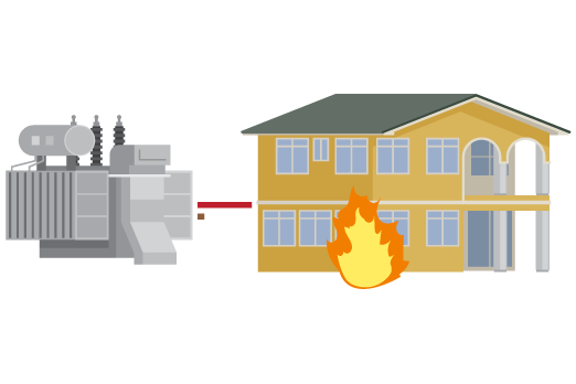
6Kva Autotransformer
 

I was demonstrating the current ratios to show the differences between a "variac" and an isolation transformer.

From the current ratio's you can realize a reduction in primary winding size and the reduction in mutual flux and thus reduction in core size and thus reduction in product size.

I think it is a reasonable deductive sequitur.

The key confusion was your insisting the windings are isolated.
They aren't and could be continuously wound with a tap almost in the middle then wires cut and reverse connected.

Practically, they are separate wires of different guage wires but coaxially wound on the same core.

To drop the voltage from 252 by 15 volts is almost a 1: 1 transformer (n=0.9). So the reduction in size is not significant in windings volume as it is in core volume. Looking at the current ratios, one can read the current ratios. However the power [W] consumption is slightly higher. for the same load.
 
Last edited:

Isolated construction - so that one can easily change it from bucking to boosting - else it can only be one or the other

I think I used the word construction, apologies if not. A standard 230: 30 Tx ( with isolated sec per usual ) is very handy in this regard, as you can then have 200V or 260 V ac ....
--- Updated ---

p.s. the opposite of non-sequitur is I think just sequitur
p.p.s. Yes I was proving your fallacy by my sequitur . The fundamental construction does not matter except for cost reductions possible. I varied Lp over a 10:1 ratio but it is the differential reduced flux and resulting excess core margin that leads to size reductions possible, but optional. It is simply the orientation of windings, and inverted winding ratio 1-(10:1) vs (10-1):10 for n=10/9
It could be the same Mk, and construction with isolated leg windings or non-isolated like a variac but reversed after the tap with similar results as you ought to know before as I do now.

Thankyou for your insights.
--- Updated ---

I realized many years ago that India and that region have such poor load regulation and blackouts that so many use linear conditioners, basically fixed tap variacs with relays. Such that when voltage dips , they boost voltage which demands more current resulting in a positive feedback effect on the grid and making it more unstable and worse load regulation for the others and contributing to blackouts.

Whereas where I live and most of North America automatic tap changers are only used to regulate the source with 5% and the distribution within 5% but residential is nominally within a few % all day, every day in Toronto. There must be exceptions that I don't know about. When I worked at Burroughs in Winnipeg, I think we were the biggest electricity client of Manitoba Hydro. I had about 20 mainframes under my group to test all the large 14" disks back in the 80's, 3 clean rooms a large PCB shop and thousands of different products with specialized testers when I was Test Engineering Mgr.
 
Last edited:
Thanks, this is all very interesting. Also, i am wondering if the autotxfmr here, is being used partly to reduce backfeeding of the household solar generation back to the grid?...(instead its wanted to go to the household battery)

I mean, when a household's GTI is inverting off the household's solar panel, there is nothing to stop that electricity from going back out to the grid?....its just the greater wiring resistance to the loads elsewhere on the grid that stops the electricity from getting exported back to the grid?...but inevitably some of the solar generation will go to the grid...this cant be avoided?
 

One question of the original post hasn't been yet answered. The typical size of a torroid autotransformer stepping down 6 kW input by 10% is 140 mm diameter x 70 mm height (600 VA transformer size). We could use it, if the GTI doesn't work with 240V + x percent.

A GTI is by operation principle tied to the grid and tries to convert the available input power. Why would you want to throttle the output power of a solar inverter? Please clarify your use case.
 
A GTI is by operation principle tied to the grid and tries to convert the available input power. Why would you want to throttle the output power of a solar inverter? Please clarify your use case.
All we want is that when the house solar panels are generating, or when the house battery is discharging, then we want to minimise the current flowing (exporting) to the grid. We want instead, as much of the current as possible to flow into the house loads.
--- Updated ---

wrong way round - as it's stepping up back to the mains, it will export more not less ...
Thankyou yes, i thought as much, with an autotransformer as described, the grid will look like a lower impedance than it is, so this would mean more export of electricity to the grid...

I am wondering, what is it about mains grid tied inverter circuits that means they needs the mains voltage to be stepped down by some 5 to 30VAC?...i mean, it cant be the switching FETs.....you can get suitable FETs with eg 650V rating, and even SiC FETs at 1200v rating......is there something in the grid tied inverter being more easy to control if it has the autotransformer at its output, going back to the grid?
 
Last edited:

If you are near to a fixed supply transformer - your mains voltage may be nearer to 240-250V most of the time - stepping down with an auto-tx may be a good idea in these circumstances
 
Thanks, though wouldnt you think that instead 1200V SiC FETs could be used in the inverter?....(with enough cooling.)
 

Thanks, and thinking of 450V electro's, then 285VAC gives 403Vpk......you could set the inverter DC bus to 430V...and still have 20V of margin. Any more than 285VAC would be from a lost neutral......and if that happened then as you know, we'd be looking at up to near 600V line to neutral....which , even with the slight_step_down transformer, would still blow up the inverters electro's?

Though anyway, from what you describe, then you would expect all grid tied inverters (for 220-240VAC) to have a low ratio step down transformer upstream of them, and i dont think most do?
 

Thanks, i am not sure if i described the context correctly....i am speaking of a house with a GTI in it, which is pushing electricity on to the phase from a battery in the house. If the neutral is lost, (ie, the neutral upstream of the house on a TN-C-S system) then that houses's phase to neutral voltage can go up to around 600V....since the GTI is connected to the phase, then surely it will see this 600V?
 

Loss of neutral is a fault condition, a topic for risk analysis and design of protection means, but not for GTI voltage rating.
Though anyway, from what you describe, then you would expect all grid tied inverters (for 220-240VAC) to have a low ratio step down transformer upstream of them, and i dont think most do?

Transformer is a last ressort when the GTI can't work with the actual grid conditions. I'd prefer an inverter with appropriate rating.
 
if the neutral is lost, there is no return path, hence the voltage seen by the single phase GTI is zero

Thanks, i dont know if i explained the context well enough, sorry about this, i am speaking of loss of neutral in the supply where it is a 3 phase supply. And the loads are well unbalanced. Each house is just receiving one phase, but loss of neutral upstream will result in a high phase to neutral voltage, which will be seen by everything in the house thats connected to phase and neutral, including the GTI, i believe you would agree with this?
 

Status
Not open for further replies.

Similar threads

Part and Inventory Search

Welcome to EDABoard.com

Sponsor

Back
Top