Continue to Site

Welcome to EDAboard.com

Welcome to our site! EDAboard.com is an international Electronics Discussion Forum focused on EDA software, circuits, schematics, books, theory, papers, asic, pld, 8051, DSP, Network, RF, Analog Design, PCB, Service Manuals... and a whole lot more! To participate you need to register. Registration is free. Click here to register now.

660v to 24v 5 a smps?

Status
Not open for further replies.

mohammad hassanzade

Newbie level 6
Newbie level 6
Joined
Oct 2, 2010
Messages
12
Helped
1
Reputation
2
Reaction score
1
Trophy points
1,283
Location
tehran,iran
Activity points
1,362
hi
i can design a switching power supply with a top switch
rating this design :
220v input
8v 5a output

but now
i need a power supply converter 660v to 24v 5a

& i question from all friends:
can i do make 3 number of my design power supply in series mode connecting in input & output for achieve to 660v input power supply & 24v 5a output power supply?

tnx for your answer before answering :D
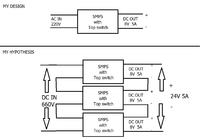


That's not sufficient. The converters must show self balancing behaviour, but they actually are sinking constant input power. Thus a converter with a minimal smaller input voltage will draw higher current which in turn further reduces the input voltage. In other words, the operation point is unstable.
 
but continue power in input & output is equal or go to equal because in output a series current use to load ?

so not stable input & output after a time ?
 

FvM is correct, there is no way to enforce power sharing between the three converters. They will all try to balance their output voltages, and the load currents will probably be equal. However, if their efficiencies are not exactly the same, then the one with the lowest efficiency will start to eat more power on its input. This will cause that converter's input voltage to drop, which causes its input current to increase, and thus you have a positive feedback loop.

The only way you could make this work is if the splitting of the input voltage into 220V x3 is itself regulated, and that itself would be quite complicated.
 

Ideally and on Paper it is ok but in practice not. All the three will never be ideally equal hence creating instability.
 

tnx for your reply

i test 2 converter in series mode with 220v
voltage in 2 input is 110v & 116V
& output voltage is true

but now
if series 3 converter in 600v
do you think a dangerous work?
 

No one said it is dangerous. All we meant is that this may not be STABLE and if any on them shows instability, will definitely be transmitted on the output.
 
At worst, the instable behaviour will cause most of the input voltage dropping across one converter stage, causing a chain reaction which finally destroys all three converters. I keep my opinion, you need an explicite balacing circuit.
 

You can use auto transformer wound for 660v with two equal tapping in input(220v each) for balancing with small power ratings.
 
Last edited:

Match identical supplies. Some sharing can be done with resistive network for eample 3, 47k resistors in series if its ok with extra power load.
 

i test 2 converter in series mode with 220v
voltage in 2 input is 110v & 116V
& output voltage is true
These converters were used on load or just tested for output voltage. If tested on load for how long in their full capacity ?. Did you monitor the Temperature behaviour, too ?
Once you are going to design, why do not you go for one SMPS from 600 volts (DC) input to 24 volts 5 amperes. You have to modify the Transformer and the output transistor, use 3845 for driving (my suggestion). But still you are the FINAL judge for your design.
 

Putting power supplies in series on the input side will only give you blow ups!

You need a properly designed psu to handle the high VDC input such as those designed by preston consulting ltd.
 
Status
Not open for further replies.

Similar threads

Part and Inventory Search

Welcome to EDABoard.com

Sponsor

Back
Top