Continue to Site

Welcome to EDAboard.com

Welcome to our site! EDAboard.com is an international Electronics Discussion Forum focused on EDA software, circuits, schematics, books, theory, papers, asic, pld, 8051, DSP, Network, RF, Analog Design, PCB, Service Manuals... and a whole lot more! To participate you need to register. Registration is free. Click here to register now.

5v to 230 V relay for a tubelight stalling atmega8

Status
Not open for further replies.

itznaidu

Newbie level 6
Newbie level 6
Joined
Feb 14, 2012
Messages
11
Helped
0
Reputation
0
Reaction score
0
Trophy points
1,281
Visit site
Activity points
1,375
Hi,
Recently I build a project to control the devices at my home using an IR Remote (RC5 protocol and TSOP)

I used a 230V spst relay with a 5v coil.
I connected the coil to the controller data pin through ULN2003a.

I was successfully able to switch on and off all the devices (Fan, bulb, tube light, TV).

But there is this one tube light which bugs me. When I switch on this tube light through the relay, I get mixed results.
Sometimes, other relays turn on, on their own.
Controller will stop responding (after I reset the controller it starts working again)
and this happens very often but not always.

I first thought that there is a problem with the relay board and disconnected all other devices and connected only this tubelight.
Then I realized the other relays were getting triggered because, this particular tube light was making the controller would make the other pins also high and stop the controller to respond.

I used a opto coupler between the relay and port pin of the controller. still the same result.

FYI- the controller and the relay is given power supply from a 12v adapter.


My assumption is that, since only this electrical device (tubelight) is giving problems, there must be something wrong with the tubelight and not my circuit.

help me on this..
 

Well i had similar problem, while controlling a motor the controller gets hanged. This must be because of EM interference. the choke coil of a tub light T5 is designed with a high turns coil. hence is may produce high EM during the start. this can be coupled with the circuit of your arduino or the relay IC.

to confirm this, try to separate the arduino and relays from the tube light by some distance, say 5 meters. if there is no problem, then it can be confirmed that its due to EMI.

To solve this problem, place the whole circuit with in a metal case. this can avoid much of external noises and EMIs ....
 

My tube light is on the ceiling and the switch board with the arduino and relays is 5M away.

But I will still try blocking the atmega 8 with a metal case.


I tried. But it did not solve my problem.
 
Last edited:

so its the problem with the tubelight and its choke... if this happens oly with that particular light, i would suggest you not u use it. it may cause interferance with nearby devices too.
 

hi,
indeed you are facing EMI problems, since electromagnetic interferences can be radiated (in near field by induction, or far field by higher frequency radiation....) or conducted (in the electric grid by example....), you can use shielding or EMI filters ............ or try a clever idea : since using a microcontroler , modify your code in such manner that valid commands get validated and executed all other commands (the noises) get ignored. Some kind of digital filtering .... ()

best regards
zsolt
 

if I have to overcome this problem, what can I do?

I tried on more experiment. I was doing wireless communication between two microcontrollers right below the tube light and I switched it on and off number of times. But the controllers were still working fine.


is there any possibility that the current can flow back or something like that?

I even tried replacing the choke and starter of the tube light but still the same problem.

Just to say, if this was a problem in some real time application, How can it be solved?

- - - Updated - - -

what do you mean by shielding and EMI filters?


you are saying that my controller gets hanged only because of the EMI.
Is it just because it is connected to the 230 V circuit. Or does the controller get hanged even if it is working in an independent power supply (battery).
 

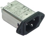
shielding means that you close your equipment in a metal box (see about Faraday's cage on wikipedia) , an EMI filter is a somple circuit containing coils and capacitors, which is conected between equipment and ac power line. Souch filter acts in both ways, for example if on the AC mains we have connected an equipment with EMIfilter, the EMI filter will stop the perturbator signals produced from our equipment to propagate thro the ac grid, but in the same time the EMI filter will protect our equipment from getting disturbed by perturbator signals coming from other equipment connected to the same ac power line . emi filter.jpg

I had the same type of problem with a 3 KW motor and a PIC16F , the controller has connected a keypad thru 10 m cable nearby the motor , and because of some interference the controller was getting false commands, since i was to lazy to find out the path of the interference i simply modified the code at the scanning of the buttons in souch way that only signals during above 10 ms and below 25 ms are validated, and all other signals are discriminated
 

Attachments

  • all_about_emi_epmag.pdf
    593.9 KB · Views: 113
Last edited:

notice that emi filters work well if you have complete wiring, F, N,GND (phase, null and ground -single-phase power supply installation of a house-) if you have only F and N and no GND, only differential noises (currents) will be filtered common mode noises not (), anyway that filter should make a difference if your neon light is producing that noise. Personally i would not buy that filter (it is not a big deal, it's just a LC filter, coil and capacitor in a little box ;-) ) , i would make a test with a home built filter ....

(to make a coil take 2 intertwined wires (F and N) and wound them on a ferrite rod, about 10-20 turns. In addition to one end of the coil put any capacitor between F and the N, you can find with ~250 Vac. nominal voltage rating . Insert the assembly between the neon light and power supply and see if there is any effect.....
... or try to put only a capacitor in parallel to your neon light's power supply terminal -between F and N- and see if there is any effect )

PS : is your neon light in a classical configuration with starter & coil, or is it with electronic ballast ?
(the classic scheme produces noise only at start-up (while starter and coil makes the ionization of gas in the tube, called 'ignition' of the tube ........) and the electronic ballast produces noise continuously since basically it's a switch mode power supply .... )

2. PS: take care when working at at ac mains, remove the voltage from the installation you are working by disconnecting the appropriate fuse at main panel, if you are not shore about which fuse disconnect's your circuit, then disconnect all fuses
 
Last edited:

Status
Not open for further replies.

Similar threads

Part and Inventory Search

Welcome to EDABoard.com

Sponsor

Back
Top