Continue to Site

Welcome to EDAboard.com

Welcome to our site! EDAboard.com is an international Electronics Discussion Forum focused on EDA software, circuits, schematics, books, theory, papers, asic, pld, 8051, DSP, Network, RF, Analog Design, PCB, Service Manuals... and a whole lot more! To participate you need to register. Registration is free. Click here to register now.

555 Toggle Starts High Sometimes

Status
Not open for further replies.

ITPhoenix

Newbie
Newbie level 4
Joined
Mar 31, 2012
Messages
5
Helped
0
Reputation
0
Reaction score
0
Trophy points
1,281
Visit site
Activity points
1,334
Hello folks.

The following circuit works perfectly, but sometimes the output will be high on power-up.

The storage cap on the 6VDC supply has a drain resistor that totally discharges the cap within 30 seconds. The problem may appear after hours of power-down/discharge.

A 10nF cap was added from pin 5 to ground to no avail.

The timing capacitor is a 2.2uF electrolytic, which gives the desired delay. It is intended to not only debounce a mechanical momentary switch, but its action is to be perceived as essentially instantaneous.

The load is a photoisolator which uses an internal LED to activate the internal MOSFET switch.
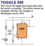
Toggle 555 Circuit .JPG

Anyone have an idea?
 

I think you could try to connect the pin 4 (reset) to the Vcc through a resistor, instead of a direct connection. Then place also a capacitor from pin 4 and GND. This should assure the 555 will always starts from 0. While the added C is charging the circuit will be insensitive to the input pulses; this blind period will be aprrox given by t=0.7*R*C
 
Implementing the suggestion with a 7 sec. delay (verified), and retesting with PS storage caps discharged, here is the result:

If the system is left in ouput low state, on restart, the output goes high a few seconds after the 7 sec. delay.

If left in the output high state and restarted, the system starts output low as desired!

This behavior is somewhat consistent.

Update: Returned to the original topology except increased the timing cap to 4.7uF and left the 10nF stabilizer in. It appears there is a lower timing limit for the example topology. The 4.7uF may be perceived as instantaneous as well.

Thank you for you help. I will make a note of your solution since it may come in handy in another circuit, or in the instant circuit with expected modifications.
 
Last edited:

Stable 555 Toggle Circuit

There were problems with a faulty pushbutton, timers of unkown quality and condition, and an unsoldered connection. After much testing, it appears the following always starts output low, and is stable.

555 Toggle Circuit - Guaranteed Low Start and Stable .JPG

It is probably overkill, but there are many unkowns in my particular application. One being open toroidal transformers in the vacinity of the circuit.

If the power is removed while in output high, and rapidly re-energized, the output will probably start high. This is remedied by installing drain resistors on the power supply reservior caps. Also, if left in output low state, unpowering then immediately powering up, the output starts high, as well!

The timing resistor could also be adjusted depending on the type of switch, and variable human interaction. Seems the range of.1uF to 10uF are all perceived as "instantaneous".

However, one must wait until the timing cap is completely charged or discharged before a successive pulse is attempted. Adjusting the 100k resistor (slightly) also seems to be an option here.
 
Last edited:

555 Toggle Circuit - Final

I do not know what you mean "buzzer for warning". I did find the culprits, though.

This goes in a tube amp.

First, I had to increase the reset delay timing cap to 10uF because it takes a long time for the system to stabilize. I monitored my tube voltages and crazy things go on until it is stable.

Second, there was some static buildup or something on the HT secondary. I exposed the two wires from the transformer to the rectifier. When I touched one of the leads, the toggle transferred to the other state. In fact, when I touched one of the tactile switch contacts, it also transferred. When touching, my body was just standing without any part of me grounded to the chassis, or in contact with any circuit conductor.

I left the 100R / 100uF filter in there, but it is probably not needed. It is designed for automotive applications, which probably suppresses alternator noise. The 10n stabilizing cap on terminal 5 was eliminated. It appears that no one indicates this cap is necessary for this application.

I have found what seems to be a better solution anyway with the IRF7319. High switching current with less parts.
Latching Toggle IRF7319 .JPG

http://www.mosaic-industries.com/embedded-systems/microcontroller-projects/electronic-circuits/push-button-switch-turn-on/latching-toggle-power-switch

There is no commentary as to the debouncing and delay periods for toggling to the other state, or if it will need some sort of delay in an application like mine. More importantly, it doesn't say which state it will start in. The "hold off" version commentary sheds more light on this kind of circuit.
 
Last edited:

Status
Not open for further replies.

Similar threads

Part and Inventory Search

Welcome to EDABoard.com

Sponsor

Back
Top