Welcome to our site! EDAboard.com is an international Electronics Discussion Forum focused on EDA software, circuits, schematics, books, theory, papers, asic, pld, 8051, DSP, Network, RF, Analog Design, PCB, Service Manuals... and a whole lot more! To participate you need to register. Registration is free. Click here to register now.
Can anyone please tell me what is the use of 555 timer circuit with a diode/resistor between charging and threshold pin, and withot any discharging capacitor. It is being used in this configuration in an amplifier power control unit?
The 555 can be put to use in a variety of ways. It has several components built into it, and a clever designer might find unconventional methods of applying them.
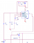
I would not be surprised if the output pin produces PWM signals for the lowermost circuit (which we do not see entirely).
In turn, an incoming line goes to the trigger pin 2. I believe its volt level rises and drops, leading to schmitt trigger action in the 555.
Looking down at bottom left, we see that incoming line goes to 12V (V3) which seems as though it would interfere. However, since we can't see components offscreen, my speculation above is all the reply I can think of.
This site uses cookies to help personalise content, tailor your experience and to keep you logged in if you register.
By continuing to use this site, you are consenting to our use of cookies.