Yuval Goldfracht
Newbie level 3

- Joined
- Jan 27, 2015
- Messages
- 4
- Helped
- 0
- Reputation
- 0
- Reaction score
- 0
- Trophy points
- 1
- Activity points
- 28
Hi,
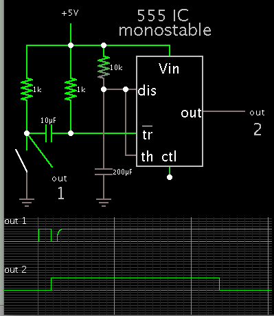
I'm trying to use the output of a 555 timer in mono-stable (one-shot) mode to control the rotation of a servo motor for a period of about 2 seconds. I'm using the RC period of the one-shot circuit to power a servo tester which will generate the pulses required for the servo. Unfortunately the circuit seems to work fine when connecting a LED to the output and trying to light it for 2 seconds but when connecting the servo tester there seems to be a problem - the tester flashes as if the voltage is inconsistent and the tester cannot perform. Attached is the scheme of the circuit with the required output function (which works fine when using a LED), the inverter an Differentiator are used to detect the rising edge of the input signal so the led/motor will work for a RC period starting from the rising edge.

Any ideas whats wrong ? How to solve ?
Thanks
Yuval
I'm trying to use the output of a 555 timer in mono-stable (one-shot) mode to control the rotation of a servo motor for a period of about 2 seconds. I'm using the RC period of the one-shot circuit to power a servo tester which will generate the pulses required for the servo. Unfortunately the circuit seems to work fine when connecting a LED to the output and trying to light it for 2 seconds but when connecting the servo tester there seems to be a problem - the tester flashes as if the voltage is inconsistent and the tester cannot perform. Attached is the scheme of the circuit with the required output function (which works fine when using a LED), the inverter an Differentiator are used to detect the rising edge of the input signal so the led/motor will work for a RC period starting from the rising edge.
Any ideas whats wrong ? How to solve ?
Thanks
Yuval