thaintrinh
Junior Member level 1
Hi,
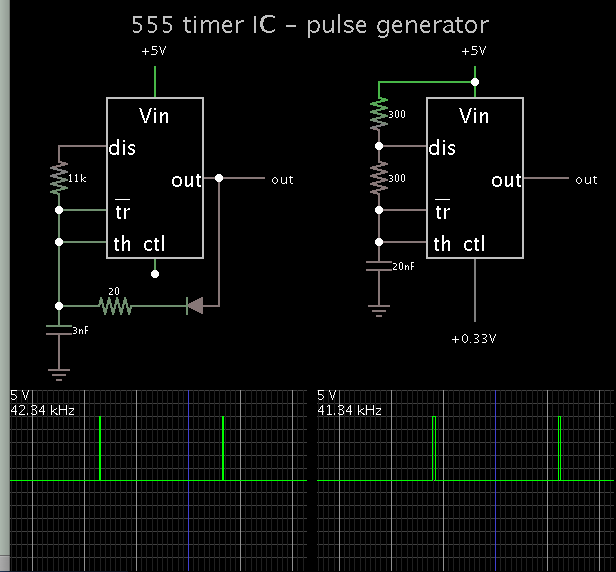
I am working on a circuit of generating a squarewave (f = 40kHz) with a HIGH time of several nanoseconds ( i.e t = 10ns) using 555 ICs. (In this case, the duty cycle is 0.04%)
I'm using a 555 monostable mode (Pic 1) with an external trigger (Pin 2).
 .
.
Here's my plan: 1st, I generate a 40kHz squarewave with a very high duty cycle(i.e 99%) (with another 555 - astable mode) and then put it in the PIN 2 of the monostable one. In this article, he's using an arduino for the 1st part.
I tested both; however, if the HIGH time is too small (according to calculation - i.e 500ns) the circuit will not work, it can only work, i'd say, bigger than 100us - this is not enough.
I also tested an astable mode one with an diode, i can only achieve a 300ns HIGH time which, is not enough...
I want to comfirm these:
_ According to theory,
_ The HIGH time : t = 1.1*R*C (R,C are from monostable part) - is this correct???
_ The 1st square wave will decide the overall output frequency and the 2nd (the monostable) will decide the HIGH time of that wave - is this correct also???
Help me pls, thank you. Finals are coming
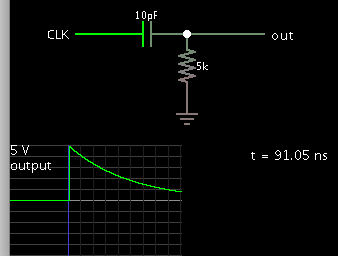
P/s: If anyone has an idea of a squarewave with the HIGH time of several nanoseconds, pls share
Thank you guys.
I am working on a circuit of generating a squarewave (f = 40kHz) with a HIGH time of several nanoseconds ( i.e t = 10ns) using 555 ICs. (In this case, the duty cycle is 0.04%)
I'm using a 555 monostable mode (Pic 1) with an external trigger (Pin 2).
.Here's my plan: 1st, I generate a 40kHz squarewave with a very high duty cycle(i.e 99%) (with another 555 - astable mode) and then put it in the PIN 2 of the monostable one. In this article, he's using an arduino for the 1st part.
I tested both; however, if the HIGH time is too small (according to calculation - i.e 500ns) the circuit will not work, it can only work, i'd say, bigger than 100us - this is not enough.
I also tested an astable mode one with an diode, i can only achieve a 300ns HIGH time which, is not enough...
I want to comfirm these:
_ According to theory,
_ The HIGH time : t = 1.1*R*C (R,C are from monostable part) - is this correct???
_ The 1st square wave will decide the overall output frequency and the 2nd (the monostable) will decide the HIGH time of that wave - is this correct also???
Help me pls, thank you. Finals are coming
P/s: If anyone has an idea of a squarewave with the HIGH time of several nanoseconds, pls share
Thank you guys.