Continue to Site

Welcome to EDAboard.com

Welcome to our site! EDAboard.com is an international Electronics Discussion Forum focused on EDA software, circuits, schematics, books, theory, papers, asic, pld, 8051, DSP, Network, RF, Analog Design, PCB, Service Manuals... and a whole lot more! To participate you need to register. Registration is free. Click here to register now.

555 Astable oscillator problem

Status
Not open for further replies.

Resistanceisfutile

Member level 4
Member level 4
Joined
Aug 22, 2012
Messages
77
Helped
2
Reputation
4
Reaction score
1
Trophy points
1,288
Visit site
Activity points
2,008
I'm using the 555 to generate square waves.
A 4 Hz wave is fine, but when I generate 4 kHz wave I get virtually nothing out of the output pin (I get about 0.04 v). Does this mean my 555 timer is broken, or do I need to increase power supply/use a transistor? (I'm powering it with a 9V battery).
 

If your 9V battery actually produces 9.0V then the output of a 555 oscillator without a load goes from 0.01V to 7.7V over and over.
Maybe your multimeter cannot accurately measure the level of a frequency so low since they are made to measure 50Hz and 60Hz.
Please post your 555 schematic.
 

It occurs as I decrease the resistance (so increase the frequency) - I am using the equation 1/(0.7*C1*(R1+R2))
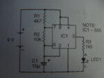
I'm using this circuit:

DSCN0057.JPG
 

There are some reasons your circuit is not working as you wish. One is that the duty cycle my be too short and you are simply not getting an out put. Another is that the resistances you have chosen may not give reliable performance. For example, AN170 (Philips, 1988) about the 555 suggests that R1 be at least 5k0. Of course 4k7 will work, but how low do you make it to change the frequency?

Before getting into a discussion of endless possibilities and alternatives, it is important that you show the actual circuit you are using and the actual component values. Which resistor are you adjusting? What is the adjustment range?

John

For R1 I'm assuming a 10k variable resistor (it has a linear scale), for R2 I use a 12k resistor and I don't use R3. Other than that I haven't changed anything.
 

Why are the values for the timing resistors so low?? The datasheets show values up to 10M.

The circuit is missing important supply bypass capacitors discussed in the datasheet for a 555. The supply bypass capacitors power the IC during its output switching when it draws a supply current spike of 400mA. Without the capacitors the 9V battery voltage might collapse.

If supply bypass capacitors (0.1uF ceramic disc plus minimum of 1uf electrolytic) are added to the circuit shown then the LED should blink slowly.
 

Attachments

  • 555 supply current spike.png
    555 supply current spike.png
    64.8 KB · Views: 172

According to an online calculator (**broken link removed** ), which I have not validated, your starting frequency with those values is about 4 Hz and the duty cycle is 65%. The high time is 0.15 s. Reducing R1 to 1K gives 5.8 Hz and 52% duty cycle. If R1 is 100 ohms (theory), then frequency is 6 Hz and duty cycle is approx. 50%. As pointed out in the previously referenced application note, your circuit with R1 = 100 ohms probably won't oscillate or won't be stable, if it does.

1) The duty cycle with that circuit must always be >50%
2) Keep R1 at >5K
3) Vary R2
4) Getting a 1000:1 frequency range may not be possible without changing more than one component value -- do the calculations
5) As AG says, you do need a bypass resistor across the supply

John

Edit: Sometime ago, I uploaded application note AN170 to EDA Board. I could not get a working link added to this message. You can search on "AN170." Alternatively, here is an outside link to the same note: http://www.sophphx.caltech.edu/Physics_5/Data_sheets/555appnote.pdf
 
Last edited:

I've found if I unplug then reconnect the battery, the LED lights up (for a moment) when set to a high frequency (that it normally fails at) - would someone mind explaining what's happening here (is this the current spike you attached)? Also, do I need to add the bypass capacitor to the other wires from the +9v, or just the 555?
 
Last edited:

Starting with the capacitor discharged, at power-up the output will be high until the capacitor charges to the threshold level (2/3 Vcc). That explanation is on page 4 of the previously mentioned AN170.

This project seems to be wandering from getting an oscillator to function. Have you read any of AN170? Have you tried any of the suggestions given to you?

John
 

Status
Not open for further replies.

Similar threads

Part and Inventory Search

Welcome to EDABoard.com

Sponsor

Back
Top