Continue to Site

Welcome to EDAboard.com

Welcome to our site! EDAboard.com is an international Electronics Discussion Forum focused on EDA software, circuits, schematics, books, theory, papers, asic, pld, 8051, DSP, Network, RF, Analog Design, PCB, Service Manuals... and a whole lot more! To participate you need to register. Registration is free. Click here to register now.

555 amplifier

Status
Not open for further replies.

boylesg

Advanced Member level 4
Joined
Jul 15, 2012
Messages
1,023
Helped
5
Reputation
10
Reaction score
6
Trophy points
1,318
Location
Epping, Victoria, Australia
Activity points
11,697
I created a 555 amplifer on my bread board tonight.

Started off with a simple NPN common emitter amplifier witha gain of 10, input impedance of 40r and output impedance of 4k.

This was just enough to get weak audio through a pair of ear buds and very weak audio through an 8r speaked. I measured the impedance of the ear buds at around 32r.

But I took the out put of this and fed it into a stock standard extended duty cycle 555 astable with a frequency of around 30kHz and duty cycle of 50%.

I got a rather powerful audio signal through my 8r speaker, although it is a bit much for the poor old 555 which heats up some what. Can't leave it going for too long.

It is working off 12V. So this bodes well for my musical plasma arc.

I am rather excited at acheiving this.


Still can't get the LM385N based preamplifier working properly. I have the gain adjustable with a 100k pot but I only get a clear signal with the pot at the top of its range. As soon as I adjust the pot the signal becomes very scratchy and staticy. It iwas running it off 24V.

Perhaps 24V is too much for the speakers to work properly and I should try it with 12V and tone down the max gain to 10 or so.
 

I think you are going well off course with all this.

1. Please explain WHY you want to amplify the output of a 555.
2. When you say the gain of your amplifier is 10, is this voltage gain, curent gain or power gain?
3. What on Earth values are you using to get an input impedance of 40 Ohms and how are you measuring the impedance of the ear buds?
4. 30KHz is too high for any Human hearing. what are you expecting to come out of the amplifier?
5. I think you confuse impedance with resistance. Check the maximum current your 555 is rated to supply (it varies by manufacturer) and see if it can supply 12/8 = 1.5A. 8 Ohms is probably the impedance at 1KHz, resistance will be even lower.

The LM385 is a three terminal voltage reference. It CAN be used in a limited way as an amplifier but isn't intended to be used that way. Can you show your schematic.

Brian.
 

...WHY...555....30KHz is too high...
Maybe he's made a class D amplifier.
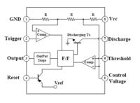
If you configure a 555 as a 30KHz oscillator, then apply an audio signal to the ctl pin, you should get PWM at the output.

Not exactly a standard circuit, but it should make a workable class D amp.
 

No, that wouldn't work. There are two controls on a 555, one changes the frequency which would create FM, not PWM, the other is a reset which is a digital input and at most would chop the oscillator output on audio peaks.
A 555 can be used to make PWM but it involves either an additional clock oscillator or an additional comparator gated with the ramp signal. This doesn't seem to be the case here.

Brian.
 

No, that wouldn't work. There are two controls on a 555....
I was thinking of using pin 5 as an input. Normally it's left unconnected, or just bypassed to earth with a capacitor. However I'm pretty sure that a change to the DC voltage on that pin would result in a change to the duty cycle (and probably frequency as well). If so, then AC coupling an audio signal to pin 5 should result in PWM of the output.

As I said: not exactly a standard circuit, but it might work (although I wouldn't expect great audio quality).


No doubt there would be some change in pulse width but it would be realtively small compared with the frequency shift. Pin 5 is internally biased but can be overridden by feeding an external voltage in. All it does is change the comparator threshold so the discharge cycle starts at a lower or higher capacitor voltage and hence the frequency of charge/discharge cycles changes.

To get PWM directly from a 555 the only way is to use it in monostable mode and trigger it from a fixed external clock frequency. Pin 5 will then adjust the width of pulse each time it gets a trigger from the clock. Alternatively, the 555 can be used to generate a near triangle wave and a comparator can then compare it to the input signal.

Brian.
 

I think you are going well off course with all this.

1. Please explain WHY you want to amplify the output of a 555.
2. When you say the gain of your amplifier is 10, is this voltage gain, curent gain or power gain?
3. What on Earth values are you using to get an input impedance of 40 Ohms and how are you measuring the impedance of the ear buds?
4. 30KHz is too high for any Human hearing. what are you expecting to come out of the amplifier?
5. I think you confuse impedance with resistance. Check the maximum current your 555 is rated to supply (it varies by manufacturer) and see if it can supply 12/8 = 1.5A. 8 Ohms is probably the impedance at 1KHz, resistance will be even lower.

The LM385 is a three terminal voltage reference. It CAN be used in a limited way as an amplifier but isn't intended to be used that way. Can you show your schematic.

Brian.

1) I am not trying to amplify the signal from the 555. The purpose of the exercise was to make sure my bjt pre-amplifier worked with the 555 pin 5, i.e. that I had an output impedance that worked with the input impedance of the 555 pin 5. As such I just hooked the 555 pin 3 up to an 8r speaker to see if the square wave carrier was being modulated successfully. My real intention is to replace the speaker with a mosfet gate driver, mosfet and flyback transformer.

2) It is a common emitter amplifier so voltage gain. The ipod is putting out some where around 1V peak signal I think so my pre-amplifier should lift it to perhaps around 10V peak and since my 555 is runing off 12V, that should be about right for pin 5. Some one else suggested the gain should be about 10.

3) I am using transistoramp software to design the the class A preamplifier. In this you specify an input impedance and an output impedance and it does all the calculations for you:
specify-common-emitter-circuit.png


4) The carrier signal from the 555 needs to be of a high enough frequency so as not to be audible, otherwise you would hear a tone superimposed over your audio signal from the ipod. In most examples of musical plasma arcs people just feed the audio signal directly in to the 555 from the ipod resulting in a fairly weak audio signal coming from the arc. So I thought I would try amplifying it a little before passing it into the 555 to see if I can get a stronger audio signal.

5. The max output current of most 555s seems to be about 200mA. This temporary amplifier I made with it is not a proper amplifier. The idea came from an example 555 circuit that was purely for demonstration (pulse width modulation) purposes and where the author stated that you can't run it for too long without damaging the 555. But I have seen other examples where the author has the 555 driving a complementary pair which in turn drives the speaker. I guess this would be a more appropriate 555 amplifier arrangement, but my aim here was not to create a proper 555 amplifier rather just to test the compatibility of my class A preamplifier with the 555 pin 5.

- - - Updated - - -

No, that wouldn't work. There are two controls on a 555, one changes the frequency which would create FM, not PWM, the other is a reset which is a digital input and at most would chop the oscillator output on audio peaks.
A 555 can be used to make PWM but it involves either an additional clock oscillator or an additional comparator gated with the ramp signal. This doesn't seem to be the case here.

Brian.

I have seen plenty of people commenting that the 555 does a very similar thing to PWM. I just looked it up and it is suppoed to do this sort of thing to the carrier signal:

http://ampcircuitschematic.blogspot.com.au/2011/05/fm-moulator-with-ic-555.html

Not quite PWM I suppose, but also not quite FM, as I understand, either.
 

Status
Not open for further replies.

Part and Inventory Search

Welcome to EDABoard.com

Sponsor

Back
Top