Continue to Site

Welcome to EDAboard.com

Welcome to our site! EDAboard.com is an international Electronics Discussion Forum focused on EDA software, circuits, schematics, books, theory, papers, asic, pld, 8051, DSP, Network, RF, Analog Design, PCB, Service Manuals... and a whole lot more! To participate you need to register. Registration is free. Click here to register now.

[SOLVED] 500va modified sine wave smps inverter

Status
Not open for further replies.

--BawA--

Advanced Member level 1
Joined
Nov 28, 2012
Messages
479
Helped
43
Reputation
86
Reaction score
42
Trophy points
1,318
Location
Noida, INDIA
Visit site
Activity points
4,931
Hii
I have to make a modified sine wave inverter.
I have generated 311vdc successfully.now my aim is to convert this high voltage DC bus into MODIFIED SINE WAVE..
I am comfartable with mcu as well as anyother analog ic. So plz give me idea how to start with??
 

if i drive my hbridge circuit by modified sine wave (quasi) ,will it work,? i mean first of all i will turn on my one mosfet pairs diagonally then turn off all the mosfet ,after that turning on the other pair of mosfet diagonally.?
will it work?
 

i have successfully designed modified sine wave inverter and it's working now ,,now i'll work on pure sine wave ..
 

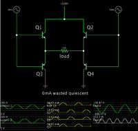
This simulation shows (theoretically) the easiest way to arrange the transistors/mosfets, and what waveforms should be applied to the bias terminals.


The control signal must reach within 0.6V of the high and low supply rails.

There is no wasted current.

It is also possible to arrange the transistors with NPN and PNP reversed, but then it will be tedious to adjust the bias waveforms properly.
 

Status
Not open for further replies.

Similar threads

Part and Inventory Search

Welcome to EDABoard.com

Sponsor

Back
Top