neeteen09
Newbie level 5
Hi everyone,
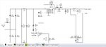
I am designing a 4W AC/DC converter using Tiny Switch III family using PI Expert software.
I got the circuit attached herewith.
I choose setting in PI software as follows:-
Output Power- 0 to 5W
Input Type- Universal 85 to 265 V
no of outputs- 1
Isolated Supply - Yes
Output Type- CV/CC
Topology - Flyback
TinySwitch-III Family
Enclosure - Adapter
Operation Mode:- CV/CC
TinySwitch IC - TNY274PN
circuit is attached herewith.
What is the significance of L1,L2 , C1 & C2 int circuit ?
Please help.
Thanks in Advance.