Continue to Site

Welcome to EDAboard.com

Welcome to our site! EDAboard.com is an international Electronics Discussion Forum focused on EDA software, circuits, schematics, books, theory, papers, asic, pld, 8051, DSP, Network, RF, Analog Design, PCB, Service Manuals... and a whole lot more! To participate you need to register. Registration is free. Click here to register now.

400W AC Servo noise surpression

player80

Full Member level 2
Joined
May 31, 2013
Messages
122
Helped
0
Reputation
0
Reaction score
1
Trophy points
1,298
Activity points
2,419
Hi,

I have installed a 400w servo on a portal but after some time it seems like that the servo is losing the position due to noise it seems, it's just a few steps the result will be that the gantry will be off for like 0.5mm after 20 min operation.
When measuring with the oscilloscope I see some noise spikes on the DIR / STEP pin interface.

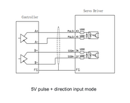
The system is controlled via a microcontroller board which is connected to a buffer (74xx), the buffer is connected to the external servo driver.
In the servo driver manual I saw that the input is meant to be driven via a differential signal, is that really a common way to connect to servo drivers? (could someone tell me which IC to use to generate a differential signal for such a purpose?) The input is supposed to be 5V.

Aside of that there's another problem at that location that there's no grounding available where the machine is deployed, I know that this can be potentially dangerous but I have to get through that before I can move the equipment.

In case this is not the right place to ask about high voltage ac servos, can anyone recommend a better place to ask?
I certainly still have to learn quite a bit about that topic. I'm currently away from that setup for 3 weeks (so I cannot show any pictures or oscillator plots before I go to that place again).
 
You ought to be using shielded twist pair or STP cable. I have seen some large pick-N-place machines use large ferrite chokes on their servo lines.
Do you remember should they be placed in front of every servo driver?

is the shield connected to the servo or to the controller or both?
 
Ferrite depends on f and current and level of EMC needed .

The "CNC-shield" is a 3ch 2A daughter-board that plugs into the NANO which uses the same CMOS bridge drivers.
How long are cables?
What is your motor driver now?
What is the motor? 400W · 200V · 2.6A?

Maybe all you need are STP cables and PE gnd to controller.
 
Last edited:
Ferrite depends on f and current and level of EMC needed .

The "CNC-shield" is a 3ch 2A daughter-board that plugs into the NANO which uses the same CMOS bridge drivers.
How long are cables?
What is your motor driver now?
What is the motor? 400W · 200V · 2.6A?

Maybe all you need are STP cables and PE gnd to controller.

I don't have PE/GND in that room at all unfortuantely.
The motordriver is a JAND4002 (400W 220V)
The cables are probably around 1m each shielded twisted pair (the twisted pairs are not shielded). Currently I'm running RS485 through it, also 5V + separate ground to a RS485 terminated PCB on the other side which converts it to single ended again in front of the driver.

I will be back to that installation in 3 weeks so I'm just collecting some information and ideas for now.
 
Hi,

first you say:
I saw that the input is meant to be driven via a differential signal, is that really a common way to connect to servo drivers? (could someone tell me which IC to use to generate a differential signal for such a purpose?)

then:
Currently I'm running RS485 through it, also 5V + separate ground to a RS485 terminated PCB on the other side which converts it to single ended again in front of the driver.
That´s exactly the differential signal one should use.

Is it really asking too much to use a pencil and a sheet of paper?

Klaus
 
Hi,

first you say:


then:

That´s exactly the differential signal one should use.

Is it really asking too much to use a pencil and a sheet of paper?

Klaus
I attached some quick drawing about the setup it's about a pick and place machine.

Before I had some low voltage motors installed, now I'm able to have 3x the acceleration and 2x the max speed with those motors. But the additional offset of 0.5mm hurts usually I'm able to catch it by placing only a few hundred components and having a look at it. I think the forward / backward moving cancels out some of the inaccuracy.
There's no problem placing fine pitch QFNs and 0402 with it, I home the machine from time to time to get the original position back, so far I placed 20k components with this setup.

So when I'm back next time first thing I'll do is to use the 12V/24V output of the driver to power the RS485 termination.
I wonder which IC could be used for the direct differential interface? I'm using single ended now into the driver as mentioned.
 

Attachments

  • schematic.png
    schematic.png
    116.2 KB · Views: 48
  • differential.png
    differential.png
    28 KB · Views: 48
Ensure the LED drive current is say 10x the output current for reliable output saturation. One of the 2 series resistors may be bypassed if necessary.
Do you remember were the chokes in the system you saw back then installed on each single driver input? I have those 3 servos now and they're just wired up without any external filter installed.
 
Yes they were on every driver cable . When using high mu material, it raises the impedance of both lines to improve the CMRR or immunity to CM noise while a differential cap lowers the impedance with rising f to attenuate radiated noise.


You can always use the PE ground near the source to shield the cable at one end. There are many ways to solve servo or EMC issues. But the best way is to measure the cause and understand it to determine how to attenuate it. Sometimes we try to simulate the noise to determine cause/effects. Other times just swamp it with suppression and isolation.
 
I did not do much debugging yet I'm surprised that it works relatively well for the first try. I'm just collecting information what I can do.
EMC and signal integrity is on another level once you have power electronics involved.
 
If you push things to limits, you can determine margin for error.
e.g. acceleration, speed, voltage, current, load resistance, electrical noise
This represents signal to noise ratio which correlates with error rate on some log scale. I used it in design verification tests to find the thresholds of errors to nominal error-free performance. This told me how good a design behaves and even how to improve it. We understand this from analog theory yet all digital systems are analog in nature during transition and at rest. This is why all digital circuits have margins for thresholds to obtain error rates so small they do not appear in our time-frame.

Fractional stepping improves damping, vibration and resolution but degrades torque and susceptibility to disturbances.

This is how I view servo systems both analog and digital (h/w steppers & s/w etc) using margins to improve performance..
 
Last edited:
While these various ideas may help I wonder if the problem might
be more like the accumulation of small errors (maybe noise
assisted) over time. And the solution might be to "home" the
mechanism at every opportunity, "recalibrating" as it were.
That would be a software deal, good if you own the code, maybe
not so good if it's a sealed can.
 

LaTeX Commands Quick-Menu:

Similar threads

Part and Inventory Search

Welcome to EDABoard.com

Sponsor

Back
Top