Continue to Site

Welcome to EDAboard.com

Welcome to our site! EDAboard.com is an international Electronics Discussion Forum focused on EDA software, circuits, schematics, books, theory, papers, asic, pld, 8051, DSP, Network, RF, Analog Design, PCB, Service Manuals... and a whole lot more! To participate you need to register. Registration is free. Click here to register now.

4 kilometers transmission line characterization

Status
Not open for further replies.

ronzino

Newbie level 4
Newbie level 4
Joined
Jun 4, 2014
Messages
7
Helped
1
Reputation
2
Reaction score
1
Trophy points
3
Visit site
Activity points
78
Hello,
I have a problem with inductance and capacitance measure of a transmission line 4 Kilometers long.
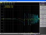
The attenuation and characteristic impedance are good, but L and C suddenly fall down and start oscillate.
In order to calculate RLGC model I have exported s-parameters touchstone file from my agilent e5061B, and processed with matlab.

The transmission line is HUGE as it will be used for energy distribution is wrapped around a metallic reel long about 15meters and with an height of 2.

what could determine the strange effect on L e C ?


capacitance.png
inductance.png
 

The diagram shows that either the model doesn't fit the measurement or your calculation doesn't converge. But without knowing the measurement, model parameters and the calculation method, it's only guessing.
 

The diagram shows that either the model doesn't fit the measurement or your calculation doesn't converge. But without knowing the measurement, model parameters and the calculation method, it's only guessing.

I am measuring using 2-port network with a full two port calibration (short, open, load on both ports and thru).
A balun 50ohm -> 100ohm is connected to each port and the to the cable.
The calibration is performed with the baluns attached to the instrument
I have set systemZ0 to 100ohm, but i think that changing it back to 50ohm will not modify the result.
the log span on frequency is from 60Hz to 10MHz with 601 points with a IF bandwith of 50Hz.
I have increased the TX power of 10dBm.

the model i have used is the following (and I think the classic one). Please note that it is quite similar to the matlab one implemented in the s-parameters to RLCG conversion function named s2rclg().

characteristic impedance calculation
Z0 = Z0strum.*sqrt( ((1+S11).^2 - S21.^2) ./ ((1-S11).^2 - S21.^2) );

K = sqrt( (1+S11.^2-S21.^2).^2-4.*S11.^2);
gamma = -(log( (2.*S21)./(1-S11.^2+S21.^2 + K) ))./lineLen;

L = (imag(gamma.*Z0))./w;

C = (imag(gamma./Z0))./w;

in alternative i have also tried the followings method (conversion from S to ABCD parameters) to calculate gamma, which leads to the same results of the previous one.

A = (1-S11.^2 + S21.^2)./(2.*S21);
gamma=acosh(A)./lineLen;
 
Last edited:

Have you checked at the S21 phase, if you have enough frequency points at high frequency?
What are your expected L' and C' ?
 

Have you checked at the S21 phase, if you have enough frequency points at high frequency?
What are your expected L' and C' ?

i am expecting about
L' = 0.58 mH/Km
C' = 63 nF/km

yes I think that i have enough point at S21 phase. I have just attached a picture

S21_phase.png
 

Unless you have the -5L3 option to extend the low range from 100kHz to 5Hz, the results are invalid.

From Telegrapher's Equation, it appears to be 100 Ohm cable making minor assumptions or Resistance/km and leakage/km
 

That S21 phase doesn't look right above 1MHz ... at least not for a low loss line.

All your equations assume a lossless line with R'=0 and G'=0. You should look at the general case where loss is included.
**broken link removed**
 

Measurements above 1MHz will be meaningless for long transmission lines.

more meaningful tests are >>10kV tan delta from 0.01 to 10Hz to determine if there is partial discharge threshold or dielectric discharge in voids is a problem, looking for small impulse discharges while measuring phase of voltage relative to low current.

since these instruments are expensive, you can rig a DC Hipot tester with a polarity switching switch at zero current , measured by a shunt R and use a linear ramp voltage to make a constant current result expected. Unexpected results would be PD and dielectric contamination or damage from carbon arcs in dielectric. With current limiting, this can be a non-destructive test.
 
Last edited:

Unless you have the -5L3 option to extend the low range from 100kHz to 5Hz, the results are invalid.

From Telegrapher's Equation, it appears to be 100 Ohm cable making minor assumptions or Resistance/km and leakage/km

i have this option;-)

- - - Updated - - -

mmmmm

are you sure that using S parameters as i have used, implies a lossless transmission line ? it is the same way as matlab use it in s2rlgc function

- - - Updated - - -

yes i know, consider the measure upper limit at 1MHz. 10MHz measure is just qualitative
 

are you sure that using S parameters as i have used, implies a lossless transmission line ?

Looking at your math again, no :sad:

I have attached some test data for you: 60Hz to 10MHz, 601 Points, lossless line with Z0=100 Ohm, k=1
 

Attachments

  • 4km_line_lossless.zip
    12.5 KB · Views: 78


From these curves it appears the impedance matching network is not calibrated. You will need two network impedance adapters for Output and Input between 50 and 100 Ohms. How does RL look after calibration with both adapters in use?

Were all the calibrations done using the 100 Ohm adapters on both ports (Baluns)? Are they rated flat to 5Hz?

It may be better to use proper;
- Impedance Matching Transformers, or
– Minimum Loss Matching Networks (Pads)

The region below 100KHz switches at 10kHz from interpolation reading 50% higher than expected and above 100Khz reading 0 nF.

I would expect flat return loss >30 dB over the range of interest.
 
Last edited:

It looks like the calculation in pot #3 can't be right for the full range of complex S21 values. Please consider that s21 is periodical and it's impossible to determine the transmission line parameters without knowing the number of full phase periods. In other words, it can't be calculated for a single frequency point.
 

From these curves it appears the impedance matching network is not calibrated.

I have tried to perform the measure without using baluns on bot ports, and the result for L and C are the same.
What do you mean for "impedance matching network is not calibrated " ?

I have performed a 2-port cal (reflection and transmission) (open short load and thru)
Are you suggesting me to perform insted a "impedance calibration" ?
 

From these curves it appears the impedance matching network is not calibrated. You will need two network impedance adapters for Output and Input between 50 and 100 Ohms. How does RL look after calibration with both adapters in use?

I have further investigated this point.
I have removed the baluns in orther to check if the problem is generated by them.

So, I have performed full 2 port calibration using two BNCs with crocodile connectors and 50ohm reference resistance.

Then I have looked at the first frequency point where impedance and capacitance have a falldown. The problem stars where S11 and S22 have a phase jump-inversion. Look at the picture belowphase_invesrion.PNG

So I also noticed that if I disable the calibration or simply I don't perform it, the previouse phase graph remains the same. It is like calibration does not influence this measure.

After I have completed calibration, I have checked it closing port-1 and then port-2 on the reference 50ohm impedance, measuring -80dB on both S11 and S22; after that I checked the thru performance of port1-2, obtaining S12=S21= 0dB.

Maybe I am missing something during calibration and this error allows me to measure a short peace of the cable (20 meters) but not a 4Km transmission line reel.

The calibration and consfiguration procedure which I follow is:

1) set log frequency sweep betwen 60 Hz and 1MHz
2) set number of point at 601 or 1601 (to slow for fast check and measure, but i will use it in futere)
3) IF Bandwith 70Hz (again I will use 5 Hz or automatic, but for a fast check I prefer 70Hz)
4) increase transmission power at 10dBm
5) system Z0=50ohm
6) start calibration, setting a user defined calkit, performing open short load (@50 ohm) on port-1 then port-2 and at the end a thru.

Maybe the problem is in the user defined calkit ? It was defined in this way, maybe copying the SMD calkit except fot load, that was changed from std type arbitrary wit equiv ckt to polynomial:

STDs
Open
STD Model Polynomial
C0=0
C1=0
C2=0
C3=0
offset delay = 0s
offset Z0 =50ohm (100ohm when a balun 50-100 is used)
offset loss = 0 ohm/sec

Short
STD Model Polynomial
L0=0
L1=0
L2=0
L3=0
offset delay = 0s
offset Z0 =50ohm (100ohm when a balun 50-100 is used)
offset loss = 0 ohm/sec

Load
STD model Polynomial
offset delay = 0s
offset Z0 =50ohm (100ohm when a balun 50-100 is used)
offset loss = 0 ohm/sec

Thru
STD model Polynomial
offset delay = 0s
offset Z0 =50ohm (100ohm when a balun 50-100 is used)
offset loss = 0 ohm/sec


thanks for your help guys
 

If calibration of instrument and testing of short 50 Ohm cable looks normal for s21,s11,
But you must use 1:root(2) turns ratio type transformer or Balun adapt 50 to 100 ohm ports on SA and compare s21,s11 with no cable.

If results still ok now test cable.

The ripple is caused by lack of matched impedance for testing. ( one doesn't normally add 100Ohms to an ac power line just to get power, but it does cause standing waves with no load)

Last photo appears as 13kHz standing wave (1/4wave) and odd harmonics indicate mismatched impedance or unterminated cable.

then you may find where the problem lies.
 
Last edited:

The s11 phase ripple just indicates that the cable impedance is different from system impedance. The "jumping" s21 phase is what we expect from a cable multiple wavelengths long. The diagram doesn't tell about possible calibration problems. It only shows regular periodical behaviour of s-parameters for long transmission lines.

For the present problem, the only device that might need extensive calibration is the balun. For a baisc measurement without balun, I would simply use a dual 50 ohm termination, similar to a 4-port measurement of devices with differential ports. As long as you don't need to access common mode TL parameters, you still perform a 2-port measurement.
 

Status
Not open for further replies.

Part and Inventory Search

Welcome to EDABoard.com

Sponsor

Back
Top