Continue to Site

Welcome to EDAboard.com

Welcome to our site! EDAboard.com is an international Electronics Discussion Forum focused on EDA software, circuits, schematics, books, theory, papers, asic, pld, 8051, DSP, Network, RF, Analog Design, PCB, Service Manuals... and a whole lot more! To participate you need to register. Registration is free. Click here to register now.

4.7 V zener diode - Unsure what is wrong????????

Status
Not open for further replies.
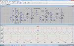
Just a further step, I make it oscillate on the simulator ;) by letting L be 120u and 20u. Hope it helps.

Please find the attached pic and files (in case you will install LTspice).

Note: About the output, I think a small diode as 1N4148, connected from it to the Vcc of the MCU, will be enough since the output resistance (10K) is relatively high.
 

Attachments

  • Colpitt_02.png
    Colpitt_02.png
    123.1 KB · Views: 80
  • Colpitt_02.zip
    2.1 KB · Views: 51
Last edited:
Remember the coil sensor technology is just as important as getting it to a reliable clock signal. try the dual D coil on ferrite yet (VLF method)
It's a huge difference, like gap sensing head for HDD.

Forget about zener with 10KΩ input or R divider to high impedance uC input clamp diode to Vdd.
 
yup .. and it is turning more and more interesting ,...
eager to keep reading ..

Well nice to see someone finds it interesting :) At times I feel like pulling my hair out when circuits don't work the way you want them to.

---------- Post added at 16:25 ---------- Previous post was at 16:14 ----------

Thanks KerimF . I will build your circuit on breadboard and check out its performance with my "inductor" . I see you have changed the two tank capacitors. I don't think I have those values in my lab. Those capacitors only affect the oscillation frequency and hence any close value should work , I think ?

---------- Post added at 16:30 ---------- Previous post was at 16:25 ----------

Also, you are taking output to the 2nd NPN from the "feedback" ?

---------- Post added at 17:02 ---------- Previous post was at 16:30 ----------

Note: About the output, I think a small diode as 1N4148, connected from it to the Vcc of the MCU, will be enough since the output resistance (10K) is relatively high.

I see the amplitude of the square wave is too high ( 9V) .
You mean a diode connecting "O12"( in your image) to Vcc pin of the PIC ?
 

I just presented a circuit to start with and please remember that simulation based on typical and ideal models doesn't reflect 100% what we may have and get on the breadboard (or PCB).

Since the frequency is relatively low, a standard general purpose NPN transistor as BC549 (or equivalent) likely provides higher gain than of BF199. In case you will use another transistor, the resistors R12 and R14 for the DC bias may need to be changed a bit in order to get the optimum bias.

Also the ratio C13/C14 is important. For high C14 (low ratio), the selectivity Q of the LC circuit will be high too (loaded less) but the positive feedback decreases.

About driving the MCU input pin, the current of the clamping diode (as 1N4148, low capacitance) from the pin to MCU Vcc (its cathode at Vcc) will be about:
(9-5.5)/10= 0.35mA.
Even if most of this current passes in the MCU diode (in parallel internally), it won't affect the pin functioning.
On the other hand you can use a zener diode instead (between pin and ground) but you need to choose its voltage as 5V6 (perhaps 6V2) to get about 4.5 V at the pin since the zener current is very small limited by R17 (for standard 400mW zeners, the typical current to get Vz is 5mA).

It doesn’t matter how many times we fail while designing a new project as long we end up with a good practical one. So the only serious failure happens when the project has to be dropped for ever ;) But even after every complete failure, we have a better chance in choosing another project which is more realizable. For instance, I cannot count my failures (silly and serious) before launching any new product. The irony is that those who use my products think I am genius ;)

Kerim
 
Thanks all. I now have a circuit that is behaving "properly" :)
 

nice to hear that ..
shall like to know what the solution was
did you change the transistor ... or made changes in your oscillator
 

First I built the circuit presented by KerimF on a breadboard and it worked fine. After few days I had some free time , so I ended up fiddling around with my old circuit and randomly tried few resistor values (in the final voltage divider) and a particular set worked for me. It was liking hitting a jackpot. Using 2 resistor instead of the zener was your initial suggestion , wasn't it? :p

---------- Post added at 09:46 ---------- Previous post was at 09:35 ----------

My oscillator was working properly for a range of inductor values so I didn't change it. It was the "squaring" up of the sine wave that was creating problem.
 

Status
Not open for further replies.

Similar threads

Part and Inventory Search

Welcome to EDABoard.com

Sponsor

Back
Top