Continue to Site

Welcome to EDAboard.com

Welcome to our site! EDAboard.com is an international Electronics Discussion Forum focused on EDA software, circuits, schematics, books, theory, papers, asic, pld, 8051, DSP, Network, RF, Analog Design, PCB, Service Manuals... and a whole lot more! To participate you need to register. Registration is free. Click here to register now.

3rd order Chebyshev Bandpass (type1) Design Problem

Status
Not open for further replies.

Faithnic

Junior Member level 1
Joined
Jun 7, 2009
Messages
17
Helped
0
Reputation
0
Reaction score
0
Trophy points
1,281
Activity points
1,389
I am not a RF designer, mostly work with power and digital design. Was curious to make a 3rd order Chebyshev Bandpass (type1) with the help of some software from the web.

I want to use it in the TV VHF band to pass one channel and stop others.

The design parameters are:

Center Frequency: 204 MHz
Pass Band : 6M Hz
Impedance : 75 Ohm

I was using AADE Filter Design And Analysis Ver. 4.5, That gives the following component values and response.
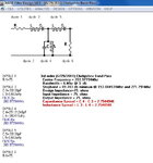
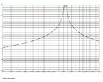
BP1a.jpg
BP1Pa.jpg

And Filter Free Ver. 13.5 from Filter-solutions.com That gives the following component values and response.

BP2a.jpg
BP2Pa.jpg

The above two software gave very different L/C values and some values are too small for practical use.

Is there any simpler practical way to find the optimum values for practical use?
 

Someone will hopefully come along with better suggestions but my feeling is that the very high Q and low ripple from a 3rd order filter are causing the problems. Try adjusting those and you will end up with something realizable. Or increase the order of the filter.

Keith
 

These types of filters are not realized with standard Butterworth or Chebyshev approximations.Because they will need so many stages to achieve bandpass and bandstop specifications.
Instead, a channel filter is practically realized with magnetically helical resonators and associated filter structures.On the internet, there are many app. notes and practical samples about channel filters.
 

As shown in a previous thread, a coupled resonator topology will result in more handy component values. https://www.edaboard.com/threads/211699/
It's also supported by the Filter Solutions Tool (at least the retail version).

These types of filters are not realized with standard Butterworth or Chebyshev approximations.Because they will need so many stages to achieve bandpass and bandstop specifications.
Instead, a channel filter is practically realized with magnetically helical resonators and associated filter structures.On the internet, there are many app. notes and practical samples about channel filters.
The standard filter prototypes can be (and mostly are) implemented by these structures (helical and such) as well. Chebyshev and elliptical filters are effectively spanning a space, where all these filters fit in.
 

As shown in a previous thread, a coupled resonator topology will result in more handy component values. https://www.edaboard.com/threads/211699/
It's also supported by the Filter Solutions Tool (at least the retail version).


The standard filter prototypes can be (and mostly are) implemented by these structures (helical and such) as well. Chebyshev and elliptical filters are effectively spanning a space, where all these filters fit in.

Theoritically yes but practically the standard filter approximations such as Butterworth and Chebyshev don't have wide tuning flexibilty.At least tuning is much more difficult than coupled filters.
Tuning needs expensive mutilturn/high qulaity variable capacitors and it won't be cost effective solution.Temperature effects will shift these components' characteristics and after re-tuning is generally needed.
In additional to, unwanted couplings between-especially-inductors and layout constraints make them practically useless.The helical filters have only mechanical constraints but thermally robust structures.

At least my filters that I have designed for VHF/UHF bands... :-D
 

If you can find an old ITT handbook there are good examples.

For this narrow a percentage BW filter you will get more realistic components with just three parallel tank with top coupling caps. That is a good design up to about 10% BW3db design. Your filter BW3db needs to be about 7.5 MHz to get <0.3 db ripple across the 6 MHz channel for a 3 pole. Try to achieve unload Q of >200 to keep insertion loss low an avoid rounding of filter nose.

A three pole is not going to give you too much selectivity. If this is for digital TV you don't want too much group delay distortion. Don't go over a 0.3 db ripple design.
 

Thanks to all for their comments and suggestions, I will come back to the issue soon...
 
Last edited:

Filter design is a little like a Rubiks cube--there are many perturbations necessary to get the final results.

In you case, where for the 2nd filter, all the components look reasonable except for one small capacitor...you got close. You can vary the filter bandwidth and try to get it a little more realizable. At this point, a true filter designer would start to add additional "impedance inverter" elements to get the component values more reasonable. You end up with more components in the filter, but it is reaslizable.

I too like the idea of three shunt L-C resonators, with series top coupling caps. You can choose an L value, then the C value goes along to resonate it at 204 MHz. If you do not like the C values in the resonator you need....just choose a different L value! The series C values, even if small, are not as hard to find/live with, as they are in a lower Q portion of the circuit and have less effect if they are a little off in value.
 
  • Like
Reactions: FvM

    FvM

    Points: 2
    Helpful Answer Positive Rating
Status
Not open for further replies.

Part and Inventory Search

Welcome to EDABoard.com

Sponsor

Back
Top