Continue to Site

Welcome to EDAboard.com

Welcome to our site! EDAboard.com is an international Electronics Discussion Forum focused on EDA software, circuits, schematics, books, theory, papers, asic, pld, 8051, DSP, Network, RF, Analog Design, PCB, Service Manuals... and a whole lot more! To participate you need to register. Registration is free. Click here to register now.

how to design e mosfet switch

Status
Not open for further replies.

upervaiz

Junior Member level 2
Joined
Mar 9, 2016
Messages
23
Helped
1
Reputation
2
Reaction score
1
Trophy points
3
Activity points
183
Hello,

I am designing a E-Mosfet (FQP3N30) as a switch. But i couldn't able to understand that, how can i design the value of drain resistance Rd.
my load is a coil valve (internal resistance is 33ohm to 70 ohm, current is 500mA) that is connected to the output of the Mosfet (drain).

Could you please tell me, how can i design my drain resistance in order to get 300V and 0V volts at the output through switching.

Thank you
 

i need to trigger my valve at the output, which needs 300V
 

300V/33 ohms is a current of 9.1A, not 500mA. 300V/70 ohms= 4.3A. Why do you think the current will be only 500mA which is 0.5A?
 

I believe the answer to this apparently confused question can be found in this previous thread: https://www.edaboard.com/threads/351735/

upervaiz missed to mention that 300V shall be only applied for a short time until a specific current setpoint is reached. The specification for the switch is rather incomplete.
 

That things has been solved by your help. but now i need to design Rd resistance because the internal resistance of this valve is very low and it can only bear approx. 500ma. I need an external resistance as well like Rd.
 

I suggest to analyze the coil and switch behavior in terms of elementary circuit theory. Up to now, your description doesn't make much sense.

- What's the intended voltage and current waveform applied to the valve?
- Do you know the inductance of the solenoid?

Saying the valve "needs 300V" is a useless specification without a timing respectively a current waveform.

I understand from your latest post that Rd is meaned as a series resistor for the valve. The resistor value could be calculated by ohms law, but dropping nearly 300 V at the resistor also implies 150 W power dissipation. So you would want to close the switch only for a very short time period, e.g. some milliseconds. These details are yet missing from your problem description.
 

The question is how can i design the rd resistance of the mosfet, as i have a shunt load connection (74ohm resistance).

1)when the mosfet is ON, there would be 300V for the shunt load only for 180microseconds.

2) when the mosfet is OFF, there would be 0V for the shunt load for the rest of the pulse.

MOSFET number is FQP3N30.
Could anyone please help me out.
 

If you apply 300 V to the solenoid, what's the current after 180 µs? If you connect a series resistor calculated for 500 mA, the solenoid voltage will be probably drop too fast and the valve never engage.
 

After the 180µs, the current is same because it's connected to another voltage supply of 9V. Valve is operating correctly, don't worry about the valve operation.

Could you please tell me, how to design that Rd resistance of the mosfet in the shunt load scenario.
 

Unfortunately I'm unable to help with the present information.

After the 180µs, the current is same
Reasoning behind this statement?
 

Sorry for the wrong statement. After 180 µs the current is approx. 200mA.
 

O.K., we can calculate a solenoid inductance of about 270 mH from the given data. The high voltage pulse duration is apparently so calculated that the solenoid current can ramp up to the steady state value fastly, but not designed to give an initial current boost.

You don't need a series resistor for the transistor if the timing circuit is working reliably. Inserting e.g. a 600 ohm series resistor limiting the current to 500 mA under all circumstances would require a longer high voltage pulse duration which is probably unwanted.

To be aware of all possible faults like load short and failure of the pulse timer, you could e.g implement a current limiting circuit together with latching circuit that blocks the output if the current limit is ever reached. Or supply the high voltage pulser from an energy limted supply (a relative small storage capacitor) together with a small transistor series resistor to handle load shorts.
 

Thank you very much for your help.

Could you please explain a bit more, where should i insert the series resistor of 600ohm. If i put in series with the load than high percentage of voltage drop is across the this 600ohm resistor not across my load (valve).

If i put like in your way than i always get the 300V at the output, doesn't matter the mosfet is ON or OFF.
 

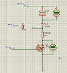
Should i do my configuration like the below mentioned image.

sch.png
 
  • Like
Reactions: FvM

    FvM

    Points: 2
    Helpful Answer Positive Rating
Completely wrong. As shown, the MOSFET is shorting the supply voltage, that doesn't work. Problem is you need a floating gate voltage to control a NMOS switch for a positive voltage, not so simple.
 

Do you have any idea, hoe this thing can be done or possible.
 

Maybe you are forgetting something. As Audioguru says, how could a valve be triggered with 300 V and can only work with 0.5 A having 70 ohms? The manufacturer would have known this...
 

Maybe you are forgetting something. As Audioguru says, how could a valve be triggered with 300 V and can only work with 0.5 A having 70 ohms? The manufacturer would have known this...
Boosting a valve voltage to increase the current fast isn't unusual. Simply think of a switched constant current with 300 V compliance. Alternatively a voltage source switched to the solenoid for a specific time to ramp the current to the intended level. Then switch to a low voltage source to maintain the current.

Problem is that the circuit in post #15 isn't a valid positive voltage switch. Not particularly related to the application, more a matter of elementary electronic circuit design. A positive voltage can be switched by a NMOS switch with a floating gate driver (e.g. opto isolated, pulse transformer) or a PMOS switch with a gate driver tied to the positive supply (more easily to achieve).

The other point was about the 600 ohm series resistor. As said, I would omit it and control the current by the "on" pulse width.
 
  • Like
Reactions: CataM

    CataM

    Points: 2
    Helpful Answer Positive Rating
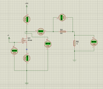
I got your point. could you please tell me that how can i switch the two voltages by using floating gate driver?

The problem, i am facing is floating point. For 300V, i have ground terminal but for the 9V, there is no ground it's floating.

shown below is image, what i got from your point. Please have a look

a.png
 

Status
Not open for further replies.

Similar threads

Part and Inventory Search

Welcome to EDABoard.com

Sponsor

Back
Top