Continue to Site

Welcome to EDAboard.com

Welcome to our site! EDAboard.com is an international Electronics Discussion Forum focused on EDA software, circuits, schematics, books, theory, papers, asic, pld, 8051, DSP, Network, RF, Analog Design, PCB, Service Manuals... and a whole lot more! To participate you need to register. Registration is free. Click here to register now.

Ringing problem in oscillator

Status
Not open for further replies.

neazoi

Advanced Member level 6
Joined
Jan 5, 2008
Messages
4,123
Helped
13
Reputation
26
Reaction score
15
Trophy points
1,318
Location
Greece
Activity points
36,955
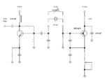
Hello I have built this HF oscillator (1-21MHz) and I monitor the output sitnal on the FFT and on a nearby ssb receiver.

I have a weird problem. When the circuit operates with a crystal, the tone on the ssb receiver is nice and smooth like it should be.
However, when the circuit operates on some inductors, the tone is "ringing". I do not know if it is amplitude variations that cause this or frequency variations.
On some coils (can transformers) the circuit does not "ring".

I power the circuit from a lab psu, regulated but not the cleanest one.
 

Attachments

  • Capture.PNG
    Capture.PNG
    5.2 KB · Views: 116

The oscillator obviously works at a critical point and Quality Factor of the inductor is not sufficiently high. Or the oscillator has a second parasitic oscillation point ( probably near to principal one ) and the oscillator "va-vient" between two points.
 

The oscillator obviously works at a critical point and Quality Factor of the inductor is not sufficiently high. Or the oscillator has a second parasitic oscillation point ( probably near to principal one ) and the oscillator "va-vient" between two points.

The oscillator is quite broadband and the frequency depends on the resonant circuit. The problem seems to appear even at the middle of the oscillation range, not just the two ends (critical points).
I have noticed that the problem is worse with cheap molded chokes.
However cheap molded chokes are desirable, since I have found that the whole HF can be covered with just 3 such inductors, by altering their core permeability using a nearby magnet.

What are the things that I can try in the circuit, in order to locate the source of the problem?
 

I think that the input impedance of the buffer is changing as the oscillator passes through some critical level or frequency. It could be that its trying to oscillate with the 100microH choke. Try a "base stopper", say 100 ohms in series and as close to the buffers base as possible. or put a resistor in series with the emitter bypass capacitor (50 ohms).
Frank
 
  • Like
Reactions: neazoi

    neazoi

    Points: 2
    Helpful Answer Positive Rating
I think that the input impedance of the buffer is changing as the oscillator passes through some critical level or frequency. It could be that its trying to oscillate with the 100microH choke. Try a "base stopper", say 100 ohms in series and as close to the buffers base as possible. or put a resistor in series with the emitter bypass capacitor (50 ohms).
Frank

Thanks, I will try both and let you know about the results.
 

I think that the input impedance of the buffer is changing as the oscillator passes through some critical level or frequency. It could be that its trying to oscillate with the 100microH choke. Try a "base stopper", say 100 ohms in series and as close to the buffers base as possible. or put a resistor in series with the emitter bypass capacitor (50 ohms).
Frank

Hi,
I have triedbfoth things. None worked :(
Is there any way that the problem might be caused by micromechanical vibrations in the specific coils?

by the way, when I vibrate the board with my hand, the unwanted modulation gets much worst.
 

As a coil in a can does not show this effect, could it be that the test coil is coupling with the choke?
Frank

I tried that. I replaced the axial molded choke at the collector with a choke of equal value wound on a toroid. No improvement.
Then I tried to remove the can from the "good" resonant coil. Indeed it had a separate ferrite surrounding the coil inside the can, so the shielding was good.
I also tried some crude shielding by a small piece of pcb grounded between the collector choke and the oscillator. Again no improvement.

Could you think of anything else to try?
 

That is weird. When I knock the resonant coil with a plastic rod the coil vibrates mechanically and the tone in the ssb receiver is severely modulated. Can it be microphonics that is causing the problem, even when the coil is not mechanicaly vibrating??
 

That's a good idea, try turning the audio up from your receiver, if its microphony , it should get worse. Try wearing phones, that should cure it.
Frank

Hi again Frank,
I tested the microphonics thing with another handheld receiver, with it's audio volume low and far apart from the oscillator.
I concluded that this is not a microphonics related problem, since this modulation did not dissapear or improved.

Would that be helpful to attach an audio file, to listen to the type of sound I am getting out of the speaker?
 

Hi, I have found the problem!
Although I do not know how to correct it...

The problem is caused by the output load impedance. If it is 50R the oscillator is ringing with the coils in place.
If it is high (a piece of wire radiating) no ringing is caused.

Any ideas of how to correct this for an output of 50R?
I would avoid using a step down transformer at the output since this will step down the output power as well.
I can provide components values if it helps.
 

Any ideas of how to correct the problem?
 

Possibly it's "squegging". That is when the oscillations build up very rapidly and there is gate rectification, driving it negative enough to stop oscillations. The gate resistor now discharges the capacitors until it oscillates again and the cycle repeats. Try reducing the gate resistor, the supply voltage or both. The output buffer will have enough gain to compensate the lower amplitude.
 
Possibly it's "squegging". That is when the oscillations build up very rapidly and there is gate rectification, driving it negative enough to stop oscillations. The gate resistor now discharges the capacitors until it oscillates again and the cycle repeats. Try reducing the gate resistor, the supply voltage or both. The output buffer will have enough gain to compensate the lower amplitude.

This corrected the problem but not entirelly.
For lower frequencies >10MHz this was ok.
However higher frequencies >20MHz or so suffered from severe ringing!

Despite this corrected the problem at lower frequencies, this does not explain why the circuit works without ringing with crystals even without this modification.
Shouldn't it be squegging with crystals as well?

What else shall I try?
 
Last edited:

After some investigation I conclude that the problem is what is mentioned on post #14.
Any ideas of how to correct this apart from reducing the source resistor?
 

If it is squegging then the you need to either limit the RF on the gate or reduce the gain of the FET. Now the pot reduces the Id of the FET, so its gain should fall but this is also altering the capacitive tap within the oscillator circuit as the input impedance to the source increases as the FET Id reduces. I wonder if putting a low value resistor in series with the source to capacitors junction would swamp this effect, though the Id would have to be higher to make up the gain. Or failing that, then a pair of back to back fast diodes connected from the gate to the source would limit the RF to about .7V peak.
Frank
 
  • Like
Reactions: neazoi

    neazoi

    Points: 2
    Helpful Answer Positive Rating
If it is squegging then the you need to either limit the RF on the gate or reduce the gain of the FET. Now the pot reduces the Id of the FET, so its gain should fall but this is also altering the capacitive tap within the oscillator circuit as the input impedance to the source increases as the FET Id reduces. I wonder if putting a low value resistor in series with the source to capacitors junction would swamp this effect, though the Id would have to be higher to make up the gain. Or failing that, then a pair of back to back fast diodes connected from the gate to the source would limit the RF to about .7V peak.
Frank

I've tried a 100R. It did not help a lot.
The greatest effect is if I replace the 220k gate resistor to ground, with a 18k. The squegging stops with some inductors then and the gain is reduced.
However I have noticed that the problem is depended in the source resistor (potentiometer). I am not entirely sure but with a setting of the pot at a position, the problem stops. When this setting is kept at higher frequencies without changed, the problem is minimized at those frequencies as well.
The weird thing is that this "ideal" setting is when the oscillator operates near the maximum power output not near the minimum.

Any ideas?
 

Squegging is caused when the amplitude of the oscillations are enough to cut the device off completely. After some time when the capacitor storing the negative voltage discharges, the device starts to conduct and oscillations start again.
The oscillator circuit is a PI network with an inductor in the series arm. At one end there is a capacitor to RF earth feeding the gate. At the other end there is a capacitor to RF earth feeding the source, whose input impedance is 1/gm. As the current through the FET increase the gm rises, so the input impedance falls and the tuned circuit gets more damped. The voltage transformation across the PI network is the ratio of the two terminating capacitors.
As the DC current through the FET increases, more negative voltage is required on the gate to cut the FET off.
Frank

This is a very useful explanation and maybe it explains why when using crystals I cannot notice this behaviour. Because maybe, due to the high Q of the crystals they cannot be damped too much compared to the coils?

Is there any way I can correct the coil behaviour, irelevant to the source potentiometer setting?

I would try simulate the thing, but I do not know what parameters to set on LTspice for the BF246C FET that the oscillator uses.
 

Status
Not open for further replies.

Part and Inventory Search

Welcome to EDABoard.com

Sponsor

Back
Top