Continue to Site

Welcome to EDAboard.com

Welcome to our site! EDAboard.com is an international Electronics Discussion Forum focused on EDA software, circuits, schematics, books, theory, papers, asic, pld, 8051, DSP, Network, RF, Analog Design, PCB, Service Manuals... and a whole lot more! To participate you need to register. Registration is free. Click here to register now.

Gain & Phase margin of synchronous Buck converter is not realistic?

Status
Not open for further replies.
T

treez

Guest
Hello,

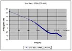
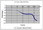
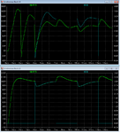
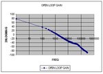
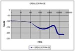
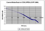
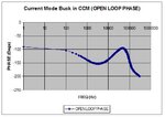
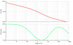
The attached bode plots of gain and phase of a Synchronous Buck Converter show that it has a crossover frequency of 3200 Hz, and a phase margin of just 9 degrees

Surely this cannot be possible?

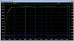
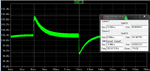
The LTspice simulation of this Synchronous Buck shows ringing after transients of around 500Hz, so the crossover frequency surely cannot be anywhere near 3200Hz?
Also, the LTspice simulation is stable with minimal, highly damped ringing after transients, so how can its phase margin be just 9 degrees?

The Power stage transfer function of this Synchronous Buck converter was calculated from equation 2A-14 of page 230 of Basso’s book “Switch Mode Power Supplies”

LTspice sim and pdf schem attached (also the bode plots, and Basso’s Page 230).


(there is no mistake in my working, I did the gain phase calculations twice and got the same result each time)
 

Attachments

  • Basso page 230.pdf
    179.9 KB · Views: 97
  • Synchronous Buck schematic.pdf
    22.8 KB · Views: 174
  • Open loop gain _Sync Buck.jpg
    Open loop gain _Sync Buck.jpg
    41.6 KB · Views: 143
  • Open loop phase _Sync Buck.jpg
    Open loop phase _Sync Buck.jpg
    39.3 KB · Views: 135
  • Synchronous Buck.txt
    12.9 KB · Views: 65
  • Synchronous Buck Excel _Feedback loop.zip
    4.9 MB · Views: 141

What is the minimum load this will ever see under operating conditions?
 
  • Like
Reactions: treez

    T

    Points: 2
    Helpful Answer Positive Rating
It was supposed to go down to no load, but as post#11 of this says….

https://www.edaboard.com/threads/349540/

…it ends up not working when the control voltage goes below a certain level because the lt1243 has two internal diodes at the output of the error amplifier, and when the inductor current becomes AC due to light loading, at some point the control voltage goes below the forward voltage of the two diodes and it no longer works.

lt1243 datasheet:
http://cds.linear.com/docs/en/datasheet/1241fa.pdf
 
Last edited by a moderator:

Yes, I saw large start-up oscillations under no-load conditions.
 
  • Like
Reactions: treez

    T

    Points: 2
    Helpful Answer Positive Rating
Thanks, youre right, that sync buck is a bogus design, provided to us by a consultancy. The sync rect control circuit is insufficient.
The attached is the right way to do it, -using a controller which never allows the sync fet to stay on for too long.
 

Attachments

  • LTC3891.txt
    5.9 KB · Views: 58

Re: Gain & Phase margin of synchronous Buck converter is not realistic?

Adding some phase boost (bottom left plot) seems to help quiet it down with no or light loads.

- - - Updated - - -

If the gain is restored that was lost by the added phase boost, the response looks nice and snappy!

- - - Updated - - -

Zoomed view of output transients.
 

Attachments

  • Synchronous Buck_phboost_plus_gain.png
    Synchronous Buck_phboost_plus_gain.png
    19.2 KB · Views: 113
  • Synchronous Buck_phboost_plus_gain1.png
    Synchronous Buck_phboost_plus_gain1.png
    35.1 KB · Views: 110
  • Synchronous Buck.png
    Synchronous Buck.png
    48.4 KB · Views: 105
  • Like
Reactions: FvM

    FvM

    Points: 2
    Helpful Answer Positive Rating
Adding some phase boost (bottom left plot) seems to help quiet it down with no or light loads.
I already thought that the presented loop compensation is far from a reasonable implementation. Looks like they should hire a consultant with a certain control theory background.
 

Looks like they should hire a consultant with a certain control theory background.
Thanks, but I dont think you've had chance to read the background on this....please let me explain.... As post#3 above indicates, all the control theory in the world will not stabilise this smps, with this inductor value, this was as discovered by Mtwieg. -as discussed above, the lt1243, with its two internal diodes, simply cannot be used to drive this sync buck...the consultancy that brought this smps forward have made a mistake.
 
Last edited by a moderator:

all the control theory in the world will not stabilise this smps
Yes and no, I guess.
No, because LT1243 isn't designed for synchronous operation and the circuit may run wild under extreme operation conditions.
Yes, because you can apparently stabilize the circuit for regular operation conditions. We would need to check with the parameters used by E-design.
 

As post#3 above indicates, all the control theory in the world will not stabilise this smps, with this inductor value, this was as discovered by Mtwieg.
Please do not attribute such nonsense to me. I've never said such a thing.

The diodes have nothing to do with the issue. The issue is that the controller can't control the peak switch current to below zero because the controller has only a positive supply. If you were to give the controller a negative GND bias, then it may work (though often these macromodels break when the GND pin is not actually at the global GND). Or you could put a positive bias on the current sense signal. There are numerous solutions.
 

Re: Gain & Phase margin of synchronous Buck converter is not realistic?

My apologies for misinterpreting Yourself Mtwieg....thing is, the controller of that simulation doesn’t care if the signal at the current sense pin is positive or negative, …the output of the error amplifier will simply depend on what is the vout….and the main fet will come on for longer if the output feedback indicates vout < wanted_vout, and the main fet will come on for less time of the vout > wanted_vout.

So if there is an overvoltage on vout (eg during start up into no_load transient), then when the simulation has L=150u, the controller is trying to control the peak current to a “positive” value which is below the value where it can actually control down to.

Your solution of making the inductor value 50uH solves this , because that gives a higher peak voltage across the sense resistor when in no load, so it can control it nicely.

- - - Updated - - -

The attached ltspice simulation with L=150uH shows this sync Buck working at both full load and no_load…this is with the help of the RC network across the upper output divider resistor, -as hinted at by E-design.

It’s “OK” in no_load, but does suffer a kind of subharmonic oscillation, which manifests as uneven switching.
However, this is “forgiveable.”

The problem is seen as the current sense RC filter getting negatively charged by the negative inductor current, so the current sense ramp starts from a lower point at first, and then for the next cycle, it starts from a higher point. If that’s what you were talking about Mtwieg then my apologies.
 

Attachments

  • Sync Buck _kind of works in no_load too.txt
    15.7 KB · Views: 85

Looks like they should hire a consultant with a certain control theory background.
Thanks, hiring an individual would mean us having to trust this individual to do a good job. Would we then need to hire another such expert to check their work?
Would it not be cheaper for us to simply use standard feedback loop equations, and then check the smps in the lab (to see if it was stable) with a frequency analyser such as the AP300 by Ray Ridley engineering.

That is, is it really wise for us to spend a fortune on a smps stability expert? -instead of doing it ourselves in the discussed manner?

If we hired an SMPS stability expert to check stability of our synchronous buck converter, then how would we know that the individual was not allied to one of our competitors?…..maybe the expert would do a deliberately poor job for us, then go and help the competitor to produce the SMPS instead
 

If we hired an SMPS stability expert to check stability of our synchronous buck converter, then how would we know that the individual was not allied to one of our competitors?…..maybe the expert would do a deliberately poor job for us, then go and help the competitor to produce the SMPS instead

If the consultant provided gain phase plots with load(s), and a report describing their work to achieve stability, then this surely would suffice? Also you could test the improved converter to verify for your self....
 
  • Like
Reactions: treez

    T

    Points: 2
    Helpful Answer Positive Rating
Re: Gain &amp; Phase margin of synchronous Buck converter is not realistic?

Yes I see your point, but of course, who's to say they didn't just check out in books what are standard bode plots for SMPS and "manipulate" their results to suit...and another point, -if they haven't done it from first principles (eg the state space analysis), and they just used standard equations, then why shouldn't we just do it ourselves.

- - - Updated - - -

-and at the end of the day, if we’re going to verify it ourselves with a frequency analyser and transient tests, then why don’t we just do it ourselves anyway……..how many times do you see an smps feedback loop get “geek hacked“ to get stability, then a quick check with the frequency analyser, transient tests , and the job’s done. –Cheap and cheerful
 

If you're that paranoid of being frauded, then you can't work with anyone, period.

That aside, bode plots wouldn't really help with large signal instability like this. Mathematically proving that a real SMPS is globally asymptotically stable is orders of magnitude more difficult than proving small signal stability. It's the kind of thing people still write their theses on.

A more feasible approach is to define a set of experimental and simulated tests which tend to catch nonlinear instability. Load and line transients, including startup with different input slew rates. The true source impedance should be considered as well.
 
  • Like
Reactions: treez

    T

    Points: 2
    Helpful Answer Positive Rating
Woops, used the wrong equation above. (used the equation for boost instead of buck)
Now repeated with equation 2A-7 of page 227 of Basso book. (Current mode Buck in CCM)
Crossover frequency now around 1200Hz and phase margin of 18 degrees. (bode plots as attached).
It still seems unusual that an SMPS with such a low phase margin has so little vout ringing at startup.

(ltspice sim also re-attached)
 

Attachments

  • Open loop gain _Sync Buck _CORRRECT.jpg
    Open loop gain _Sync Buck _CORRRECT.jpg
    34.6 KB · Views: 141
  • Open loop phase _Sync Buck_CORRECT.jpg
    Open loop phase _Sync Buck_CORRECT.jpg
    31.6 KB · Views: 148
  • Synchronous Buck.txt
    15.1 KB · Views: 72

Hello,

Finally the corrected feedback loop calculation has been done, and an RC series network has been placed across the Buck’s upper divider resistor, the Excel calculation has been corrected to have the correct switching frequency, and the Crossover frequency is now calculated as 2300Hz and the phase margin is a healthier 30 degrees, there is now no overshoot at startup of the Buck simulation (attached).

LTspice simulation also provided.

The calculation is lengthy in excel, does anybody know of a website that can be used to do this in the quicker matlab, so as to act as a checker?
 

Attachments

  • Basso 227.pdf
    131.4 KB · Views: 102
  • Basso 228.pdf
    220.6 KB · Views: 102
  • Synchronous Buck Excel _Feedback loop calculation.zip
    2.7 MB · Views: 139
  • Current mode CCM Buck _Open loop gain.jpg
    Current mode CCM Buck _Open loop gain.jpg
    42.7 KB · Views: 104
  • Current mode CCM Buck _Open loop phase.jpg
    Current mode CCM Buck _Open loop phase.jpg
    38.3 KB · Views: 134
  • Current mode CCM Buck.txt
    6.9 KB · Views: 80

At start-up the power circuit is loaded (sometimes overloaded) by the need to charge the output caps...
 
  • Like
Reactions: treez

    T

    Points: 2
    Helpful Answer Positive Rating
That looks more like it. Below is what I got the first-time round before adding phase boost.
 

Attachments

  • GP_plot.png
    GP_plot.png
    20.9 KB · Views: 99
  • Like
Reactions: treez

    T

    Points: 2
    Helpful Answer Positive Rating
Status
Not open for further replies.

Similar threads

Part and Inventory Search

Welcome to EDABoard.com

Sponsor

Back
Top