Continue to Site

Welcome to EDAboard.com

Welcome to our site! EDAboard.com is an international Electronics Discussion Forum focused on EDA software, circuits, schematics, books, theory, papers, asic, pld, 8051, DSP, Network, RF, Analog Design, PCB, Service Manuals... and a whole lot more! To participate you need to register. Registration is free. Click here to register now.

Low Pass Filter Design RC or LC?

Status
Not open for further replies.

rhnrgn

Member level 5
Joined
Dec 25, 2013
Messages
92
Helped
2
Reputation
4
Reaction score
2
Trophy points
1,288
Activity points
2,069
Hello Friends,

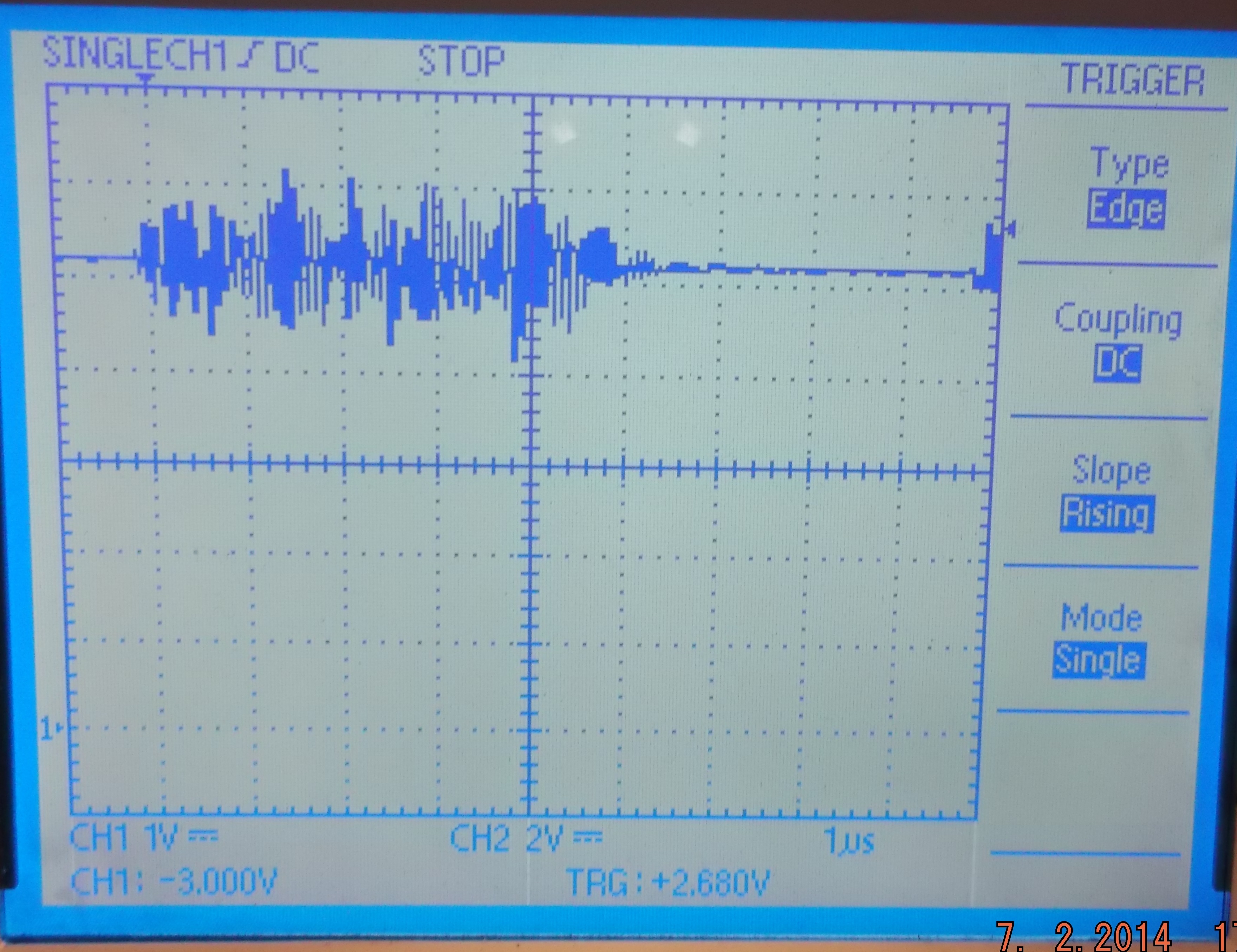
1_I am going to filter above 100Khz. Esspecially between 5 MHz-30Mhz band. Am i going to use LC filter or RC filter?

Now i have 1k Ohm and 1uf RC filter but it is not working as it is use to be in theoretically. It passes some noise above 5 MHz. I am using ceramic caps.

I am thinking about using capacitors in parallel 1uf-100nf-10nf-1nf.

2_If i dont have any affraid about voltage drop on resistance, isn't it better to use resistance instead of inductance.(I am talking about 5Mhz-30Mhz bandwidth)

Thank You
 

There are a number of things to consider. Yes, an RC filter will have some IR drop, but that depends on what your load is. If you're going into a high-impedance it doesn't matter. The RC filter you speak of has a cutoff of 160 Hz. You are using a 160 Hz filter for a range of 5-30MHz? Something is not right.

A single-pole RC filter at 100KHz will have an attenuation (theoretical)of about 35 dB. But you also have to consider parasitics in your actual circuit. I think we need more information.
 
  • Like
Reactions: rhnrgn

    rhnrgn

    Points: 2
    Helpful Answer Positive Rating
I will use that RC filter between optocoupler (6n137 fairchild) output and dspic30f6015 I/O pin.

I thought that if i use 160Hz lowpass filter it will remove every frequency above 160Hz. I have noise problem and which is passes through that RC filter. When i measured characteristic of that noise at 5 V line it is between 5Mhz and 30Mhz and 2 volts amplitude.

Another question, i found some Texas Instruments active low pass filters which are uses OP-AMPS. Do you suggest them? Cost is not important i just need to eliminate that noise because i lost alot of time.

Thank You
 

As you can easily calculate, the attenuation of the filter at 5 MHz will be about 90 dB. It seems quite obvious that the 5 MHz signal does not pass the filter rather than bypasses it somehow. But without knowing the circuit details, I can only guess.
 
  • Like
Reactions: rhnrgn

    rhnrgn

    Points: 2
    Helpful Answer Positive Rating
Above the self-resonant frequency of the component, its behaviour changes completely.
Maybe you C is no longer a capacitor at 5 MHz.
Even well below self resonance, the maximum attenuation would be limited by equivalent series resistance.
Regards

Z
 
  • Like
Reactions: rhnrgn

    rhnrgn

    Points: 2
    Helpful Answer Positive Rating
I would agree with FvM; that noise it not passing through the filter. Think about it, for you to see 2V at 5MHz passing THROUGH the filter, the input level would have to be about a trillion volts. You could be picking it up on your scope probe. You could have a layout problem.

But more to the point: 2V is not noise-that's a catastrophe. You need to step back and look at your design differently.
 
  • Like
Reactions: rhnrgn

    rhnrgn

    Points: 2
    Helpful Answer Positive Rating
Going back to your OP which mentions 100 kHz...
This is in case a smaller capacitor (smaller in value and/or physical size) will perform better for your filter...

Here is a simulation with a 1k resistor and 2.2 nF capacitor. The rolloff frequency is 72 kHz (per caption at bottom right).

The scope trace shows that practically none of the signal above 5 MHz gets through (theoretically).

 
  • Like
Reactions: rhnrgn

    rhnrgn

    Points: 2
    Helpful Answer Positive Rating
The difference is source of noise is a solneoid valve, when de-activating it happens what happens and in my system there is a huge 330V AC motor and when motor rotates also there is noise at power line with approximately same characteristic. PLC and my electronic card sources from that power line. I can see motors noise at 24V stage too.

Is there any document which tells me how to decide whether is it a resonans problem or wrong filter issue? I am newbie about this EMC problem :/

Not1: Without RC filter, noise causes RESET MCU most often, after implementing RC filter there is still RESET but decreased alot but i need to remove that RESETting totaly.

Not2: Solneoid valves as you know, pumping the voltage(energy) to notr line when they are de-activated. On the other hand i am not sure about the characteristic of AC 3-phase motor =)

I will draw a schematic and ask onther question. I hope this will enlight you about my situation.

- - - Updated - - -

This is the Optocoupler and MCU part of the schematic:


This is the power part of the MCU Power 24V in converted to 5V:


This is the noise at MCU I/O when solenoid valve activated:


Not1:Input of optocoupler is 24V.

Not2:Optocoupler works reverse. When you apply HIGH to input of optocoupler output is LOW. When LOW, output is HIGH.

Not3:There is also noise at output of power stage at 5V line but if i not connect PLC there is no reset occurs even if there is 5V at I/O pin. This shows me noise from power stage is not causes RESET.

Not4: When i connect PLC, MCU starts Resetting when that noise occurs.

Not5:Because of that reverse working, while plc is not sending any data, whether if PLC connected or not, there is 5V at I/O pin of MCU. This is also shows me noise from power stage is not only can causes RESET.

Not6:There may 2 reason:
1_Noise passes through optocoupler (i know it is very difficult, it is totaly isolated, and when i calculate CMR value it is around 500V/us it is more below CMR value of optocouplar which can handle).
2_There is noise at massage from PLC, there is also noise at 5V of MCU. Source of that noise is same , thats why frequency is approximately same but the way they reaches to I/O is different that is why there is a phase shift between them. When noise occur they may hop on them selves and increase voltage twice of noise, or increase the frequency of noise.

What an EMC problem is this, this is my first time. GOD pls dont push me that hard =)

- - - Updated - - -

Above the self-resonant frequency of the component, its behaviour changes completely.
Maybe you C is no longer a capacitor at 5 MHz.
Even well below self resonance, the maximum attenuation would be limited by equivalent series resistance.
Regards

Z

I think RC filter has no resonance frequency. LC filters has resonance frequency. If i am wrong please correct me. I have heard about behaviour of Caps in high frequencys. Do you have any document which explains this. I couldnt find any :/
 
Last edited:

Please review the suggestion about checking ground "noise" in your previous thread https://www.edaboard.com/threads/310170/#post1330346

Why are you sure that the shown intereference is injected through the optocoupler? Much more likely it's conducted by a power supply or ground connection.

The input/output coupling capacitance of the optocoupler is about 0.5 pF. The ground wiring of your circuit must be very bad to cause a reset through this path. The 5V optocoupler output signal shouldn't be able to cause any circuit malfunction under normal conditions.

A trivial explanation would be that the reset is caused by your software design.
 
  • Like
Reactions: rhnrgn

    rhnrgn

    Points: 2
    Helpful Answer Positive Rating
Please review the suggestion about checking ground "noise" in your previous thread https://www.edaboard.com/threads/310170/#post1330346

Why are you sure that the shown intereference is injected through the optocoupler? Much more likely it's conducted by a power supply or ground connection.

The input/output coupling capacitance of the optocoupler is about 0.5 pF. The ground wiring of your circuit must be very bad to cause a reset through this path. The 5V optocoupler output signal shouldn't be able to cause any circuit malfunction under normal conditions.

A trivial explanation would be that the reset is caused by your software design.

I also look at software and found that there is trap occurs before resetting. After i investigate deeply, i found that because of that spike MCU try to go a non-defined address and that is why resetting it self. I should eliminate that spike first, in addition i am taking some steps about software, "preventive coding" of course.

FVM very thank you for your reply, but pls let me ask you a question. I have only 2 power lines and no earth connection. What can i do without adding caps between them. I have no earth ground bro :/. There should be something else, because PLC is not resetting but my MCU is :(. I know i am talking like a parrot but i am really stucked and trying to find a way to out. I spent 2 months for only this issue. Everything is OK without this problem and with this problem i can not show my system as a product.

When i told my customer you dont have earth ground, he tells me but there is PLC's and computers, they are working great, in this conditions i will think again about your product ect. zzzz
 

Surely the system has more external connections than just two power lines. E.g. during test you have connected a debugging adapter or ICE, probably serial interfaces without isolation etc. All these connections are conducting interferences respectively act as a return path.

Looking at the problem from the system's side, you have a local ground and power supply. External interferences are "seen" as voltage differences to the local ground rspectively as currents injected between the ground and an external connection.

Interference strength of the circuit wil be established by the following measures (ignoring radiated interferences at the moment)
- have a continuous, low inductance circuit ground (preferably a plane) so that currents injected at one point of the ground net don't generate voltage differences to other ground points
- have either a continuous supply plane with distributed bypass capacitors, or complete bypass capacitors at each logic IC or processor supply pin
- filter each external signal against the common ground before it touches the inner circuit core, in addition voltage suppressor means, common mode filters or series resistors might be used
- isolated peripheral circuits (by optocoupler, relays, transformer) will be usually placed outside the common ground plane to minimize coupling capacitances

In-circuit measurement and debugging is a topic on it's own and may need special requirements, e.g. USB isolators, common mode filters, battery operated oscilloscopes etc.

Regarding the apparently observed address fault trap, it might happen e.g. in this situations
- you have a processor system with external memory bus (probably not)
- processor supply voltage is carrying serious voltage spikes (insufficient bypassing, bad ground wiring etc.)
- the debugger connection is picking up interferences
 
  • Like
Reactions: rhnrgn

    rhnrgn

    Points: 2
    Helpful Answer Positive Rating
actually we are using an external memory. FRAM. Because when we try to use Dspic's memoy we are loosing datas that is why we switched to external FRAM FM25C160B-G. which is communicating with SPI.
 

Status
Not open for further replies.

Part and Inventory Search

Welcome to EDABoard.com

Sponsor

Back
Top