patan.gova
Full Member level 3
Hello,
I am working with the extraction of Pulse signals using the intensity of LED(Infrared) converted to current using Photo detector (VBP104SR ) and the small current of photo detector is being converted to voltage using the Trans impedance amplifier stage(OPA380).
The designed circuit is this **broken link removed**
The output of the transimpedance is
output1:**broken link removed**
output2 : **broken link removed**
output3 : **broken link removed**
sorry for the low quality and bad signal.
The real pulse signal willl be like Actual pulse signal **broken link removed**
Sometimes the output of the transimpedance stage is showing like the actual pulse signal with some noise but mostky it is very noisy and will be very difficult for the post processing of ADC read.
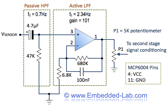
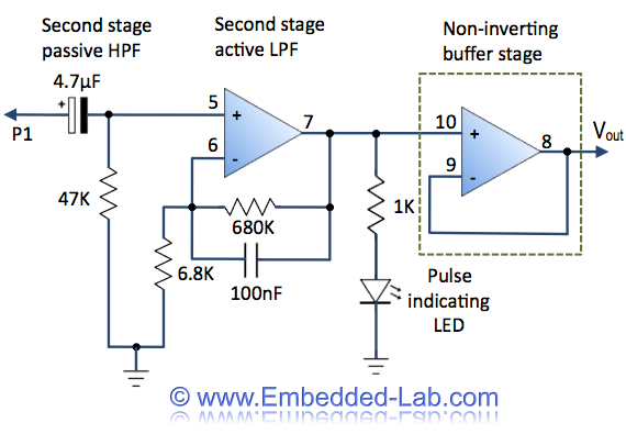
Cansome someone help me with the suggestions or corrections needed by the circuit designing of filtering or if anything is needed.
Thanks in Advance.

