Continue to Site

Welcome to EDAboard.com

Welcome to our site! EDAboard.com is an international Electronics Discussion Forum focused on EDA software, circuits, schematics, books, theory, papers, asic, pld, 8051, DSP, Network, RF, Analog Design, PCB, Service Manuals... and a whole lot more! To participate you need to register. Registration is free. Click here to register now.

30 pts. for HELP ( Final Day of Project)

Status
Not open for further replies.

cadenceUK

Member level 5
Joined
Aug 15, 2007
Messages
90
Helped
1
Reputation
2
Reaction score
1
Trophy points
1,288
Activity points
1,862


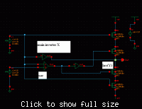
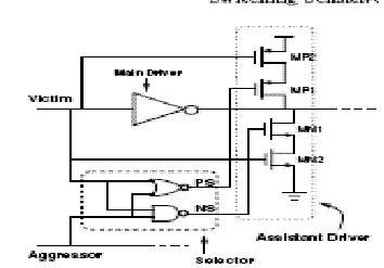
How can I use XOR gate ( as above) here to implement the following circuit?

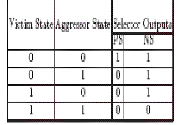
This circuit just switches the transisters on/off in case of opposite inputs.
29_1189593171.gif

82_1189593144.gif


Added after 17 minutes:

Can i replace the above circuit of nand+nor and shown truth table wid XOR gate?

Added after 1 minutes:

as my main motive is to activate the assistant in case of opposit input!

and hence to increase the drive strength!

How can i do this!!

Help will be appreciated and I will give all point 2 helper!
 

Could any one just tel me how can i turn the transister off in the top circuit when the XOR output is high?
 

Either put a NOT gate (inverter) between the output of the XOR gate and the transistor's base, or add another transistor, with its base in the first transistor's collector (parallel) - this way, it will invert. Remeber to add all the extra bells and whistles, resistors to limit current inrush through the base, etc etc.
 

    cadenceUK

    Points: 2
    Helpful Answer Positive Rating
Thx fr response!

Which transistor are you talkin about?

and what extra bells and whistels?

Thx in anticipation
 

Pleeeeeeeeeeeeease Helppppppppppppppp!!!!

I need to increase the drive of this circuit (buffer) in case of opposit bit patteren!
 

Nevermind the extra inverting transistor. Just put a NOT gate after the XOR gate, and after the not gate, a base/gate of a BJT/FET. Then drive whatever you will need from it's collector (or emitter, depending on your case) / source (or drain)
 

ne 1 there???

I want to incerease the drive of buffer in case of opposite bit patteren!( detecting here by XOR gate)


bt how can i increse the drive?? hw to switch on the transistor?

Added after 5 hours 32 minutes:

Alive?
 

Izua shows the way. About the details: How much power do you need?
 

I want to replace this circuit wid a traditional driver!

In traditional driver the drive is larger due to opposite bit pattern affecting drive strength!

Here i l increase the drive only in d case of opposite bit pattern!
 

I know how it is to miss a project or be late with it, but this is the last time i'm explaining it to you.
I'm not sure what you're saying in the last post, but it's a bad idea to do the logic (opposing bits) in the drivers.

So, first, we need to have a signal on opposing bit patterns. This is something like

Code:
A | B | res
0 | 0 | 0
1 | 0 | 1
0 | 1 | 1
1 | 1 | 0

-which is actually the xor function. So, go get a XOR gate for this. The easiest to find is in the CD40xx series.

Now, if you wire it corectly (power, inputs, don't leave floating inputs) whenever you will apply signals to its inputs, you will get the value in the table above. Correctly means 0 is ground, not floating, btw.

We have the signal, but now we need to amplify it, or make it toggle a large current/potential, since our load is a big one.
We've got several options. First, we can use a basic transistor. Base goes in the signal, with a resistor in series, collector to V+, emitter to Gnd (0) if the Q is NPN type. You put your load either between V+ and Collector or Gnd and emitter. Remember to add a resistance, too, between V+ and C, or Gnd and E, so you will limit the maximum current to the transistor capabilities.

There is another way, too - using a driver IC like from the UDN series (UDN 2981 for example). You wire V+ and GND to this driver, and to one of its inputs link the XOR gate's output.

The last, and most easy way to do is (but worst as size and reliability) is with a relay. The gate is commanding the relay (remember to put a diode to protect the gate from current that comes back from the relay when it toggles), and with the other pins of the relay you can command up to anything. AC, High frequency signals, you name it.

Hope it helps.
 

    cadenceUK

    Points: 2
    Helpful Answer Positive Rating
I intend to use the buffer inside an IC and increase the drive strength of that buffer to reduce power consumption in worst case!

How could i use a relay or something big which will consume more power than a driver itself fetches!

Thx anyways 4 ur post, support and help!

I wasnt able to express wt i intended to do i guesss!

Accept my apology!
 

The XOR (exclusive-OR) gate acts in the same way as the logical "either/or." The output is "true" if either, but not both, of the inputs are "true." The output is "false" if both inputs are "false" or if both inputs are "true." Another way of looking at this circuit is to observe that the output is 1 if the inputs are different, but 0 if the inputs are the same.


XOR gate

Input 1 Input 2 Output


input 1 inout2 output
0 0 0
0 1 1
1 0 1
1 1 0
 

you should search on google instead of crying out loud................
 

HI U CAN USE 4017 FOR THE TOGGLE AND USE 2008 FOR THE DEVICE U WANT TO ON OR OFF
 

i have an other question but its not about what your talkin about...
what does this circuit do?as far as i can understand the output is NOT `Victim` (v1 in shcematic).. am i right?
 

Who give me 30 points?

Možda zna Zvuk - Specijalac - Dačo on je ionako prepametan????
 

Status
Not open for further replies.

Part and Inventory Search

Welcome to EDABoard.com

Sponsor

Back
Top