Vermes
Advanced Member level 4

This lab power supply is based on simple design with some modifications. It uses a powerful transformer (more than 200W, 30VAC output voltage).
Features:
- switchable windings, so at low voltage and high current you can minimize power losses on the transistor
- additional transformer to power the operational amplifiers and stabilize the voltage
- BD139 as transistor Q2
- BD249C as transistor Q4
- TL081 changed into ua741
- additional potentiometer for precise voltage control
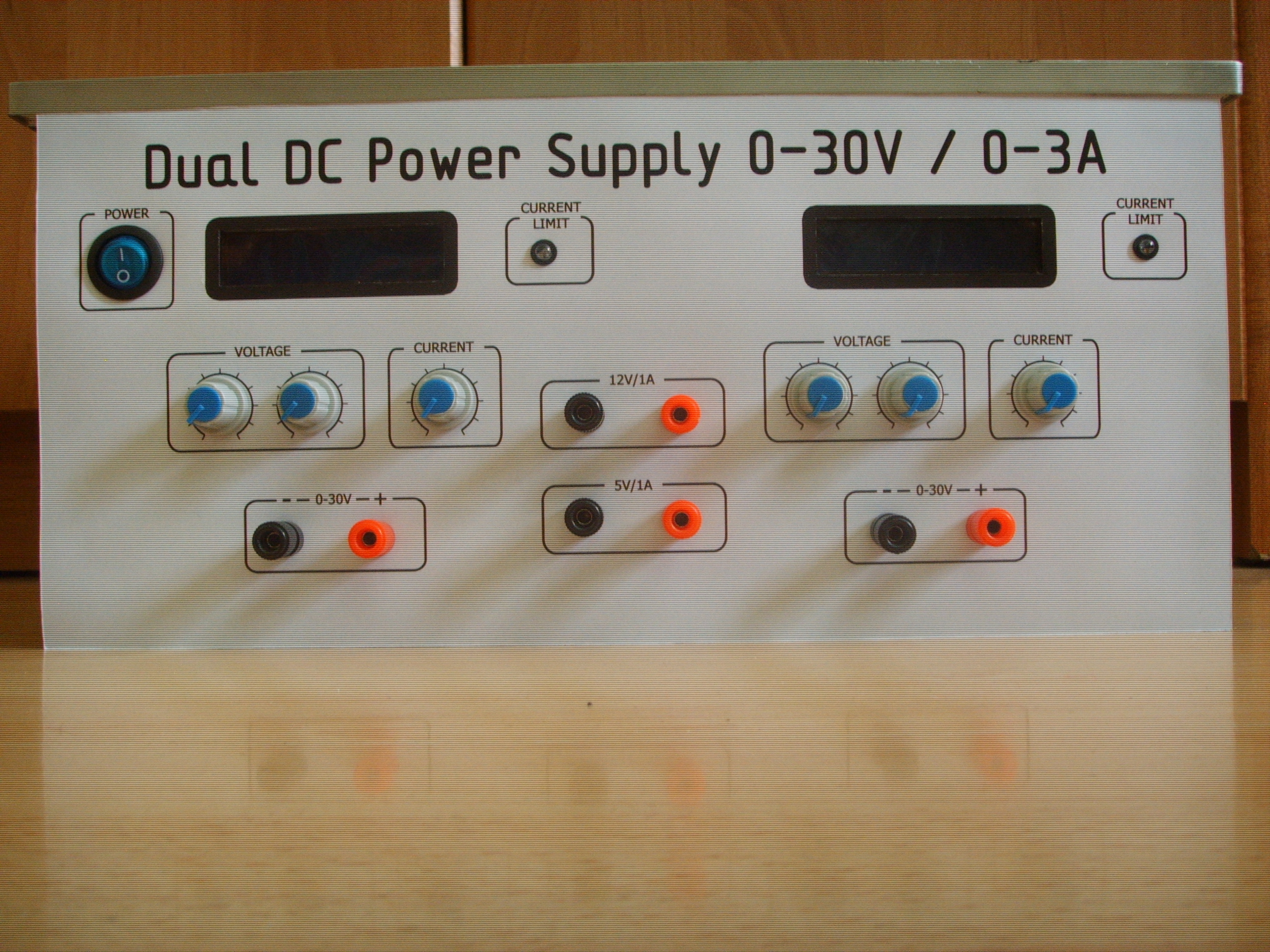
Secondary windings of the main transformer were winded again as 2x24VAC with a tap in the middle. Another transformer was removed from an old rectifier. 4 secondary windings were winded on that transformer: 2x24VAC to pwoer the operational amplifiers and to power the meters, and original windind was used to power the linear stabilizers 5V and 12V, outputs of which can be found on the front panel in the form of banana sockets.
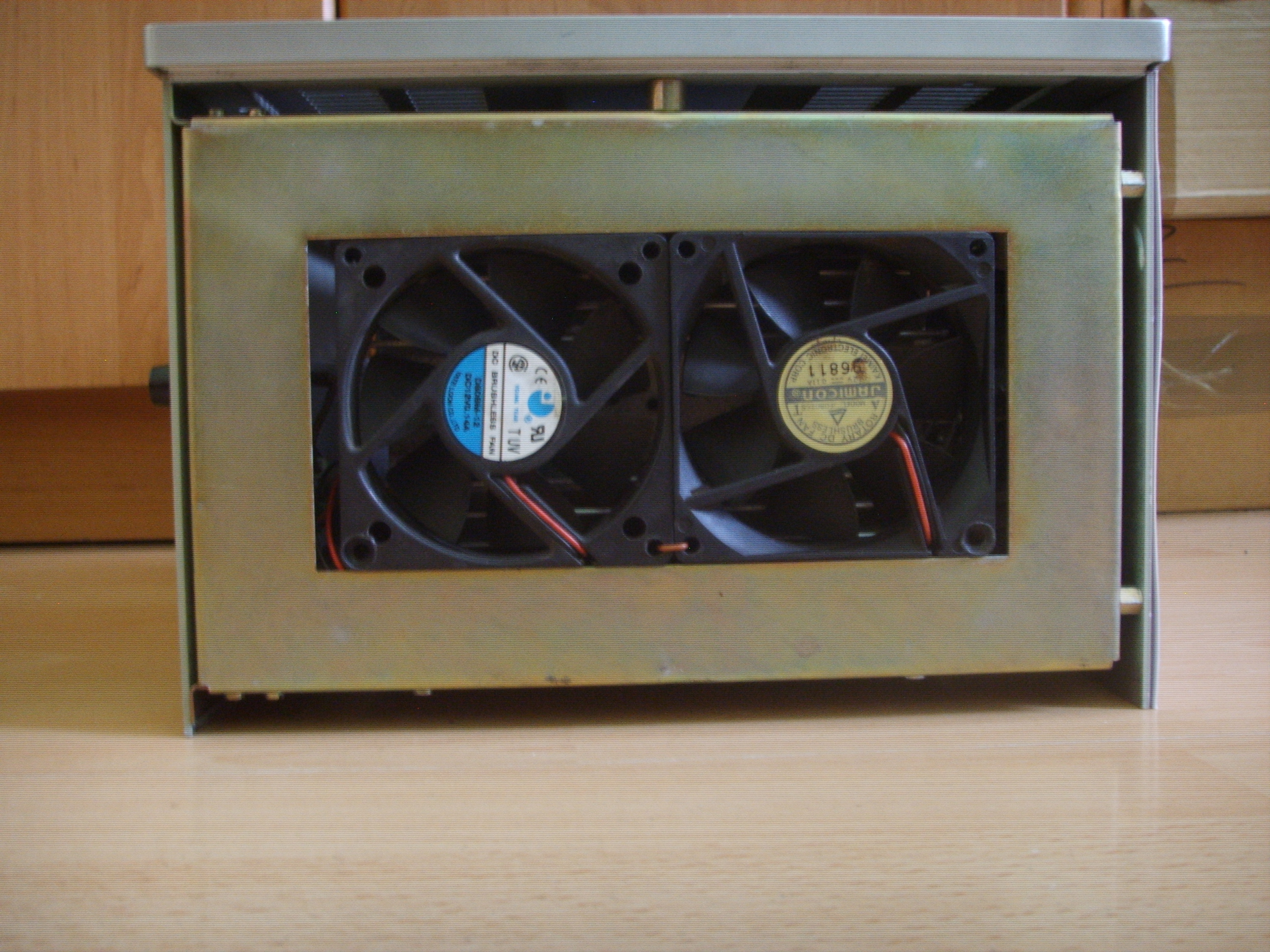
Large capacitors used in this design: 6800uF from ELWA. Heat sink was from the rectifying diodes (200A). Its base is more than 20mm thick and copes with the heat from both transistors. Resistors 5W were designed to be on the board, but they heated up too much, so they were moved to the heat sink. In addition, there are two fans from a PC, controlled by a simple regulator based on NTC thermistor, transistor NPN, resistor and potentiometer. Using the potentiometer, you can preset the temperature at which the fans start.
Metal housing was removed from a dead UVG2 generator. Front panel was designed in Photoshop except the scale of the potentiometer, which was made in Inkscape. The panel is greater than A4, so it is good to have it made to order.
In the back of the housing there is IEC supply socket and two sockets of fuses (primary side of the transformers).
Rectifier bridge was made of 3A diodes. There is a heat sink on them.
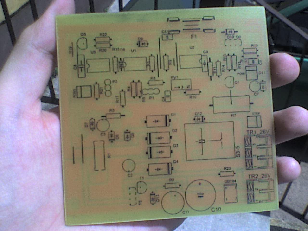
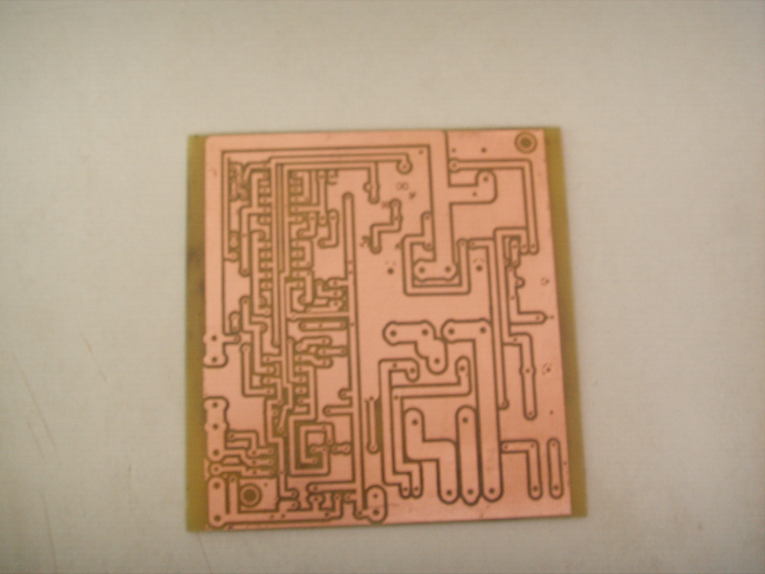
Boards were made in thermal transfer method. Using iron, which was turned upside-down, the boards were covered with laminate and print, which was tightened by a rubber roll. Descriptions were made using thermal transfer and chalky paper. After bathing in suitable solution, the whole chalk was removed, leaving nice black descriptions. All files necessary for making the PCBs (in 1:1 scale, ready for printing) and schematics are in the attachment to the original thread (link given in the end of this thread).
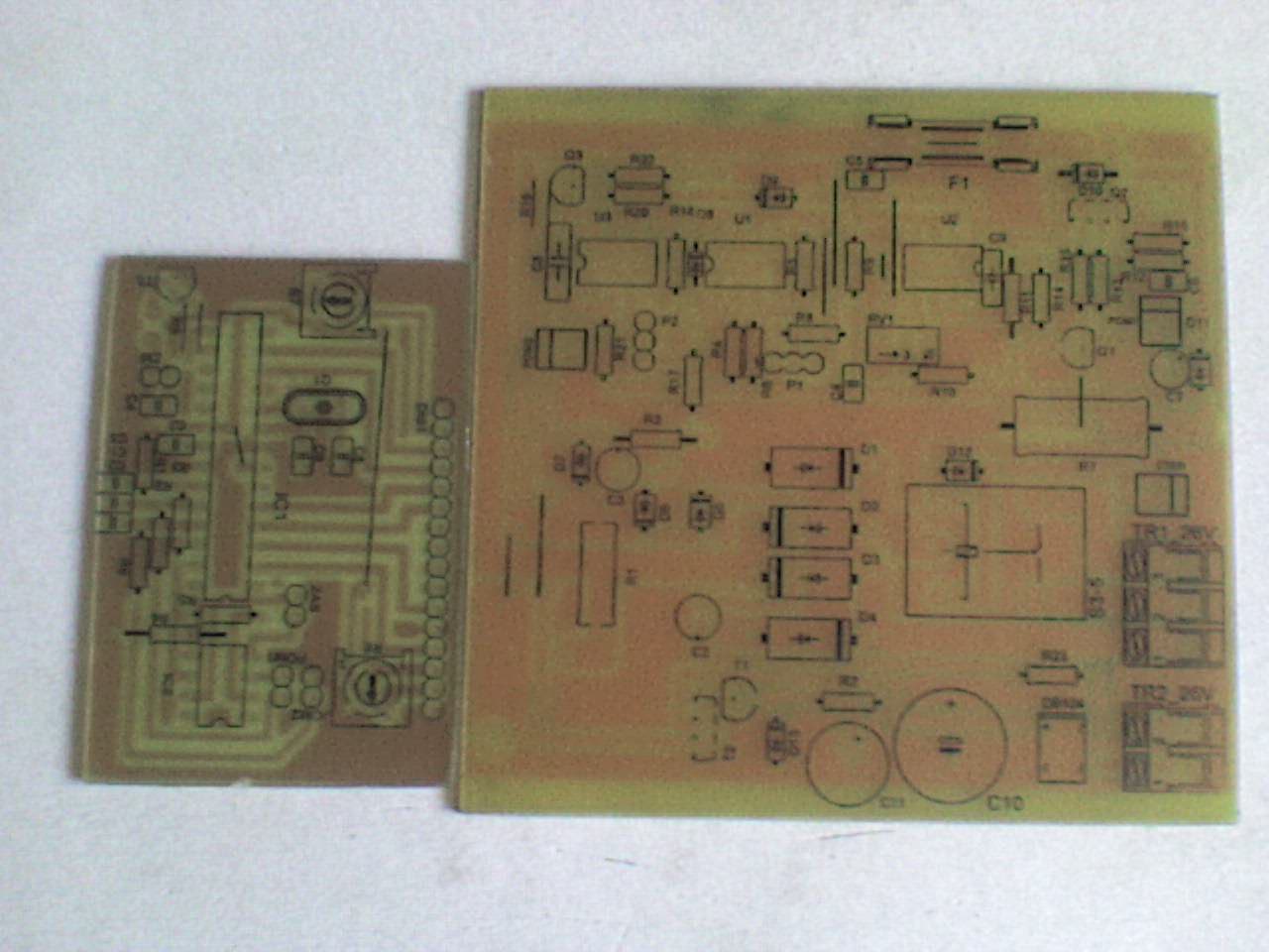
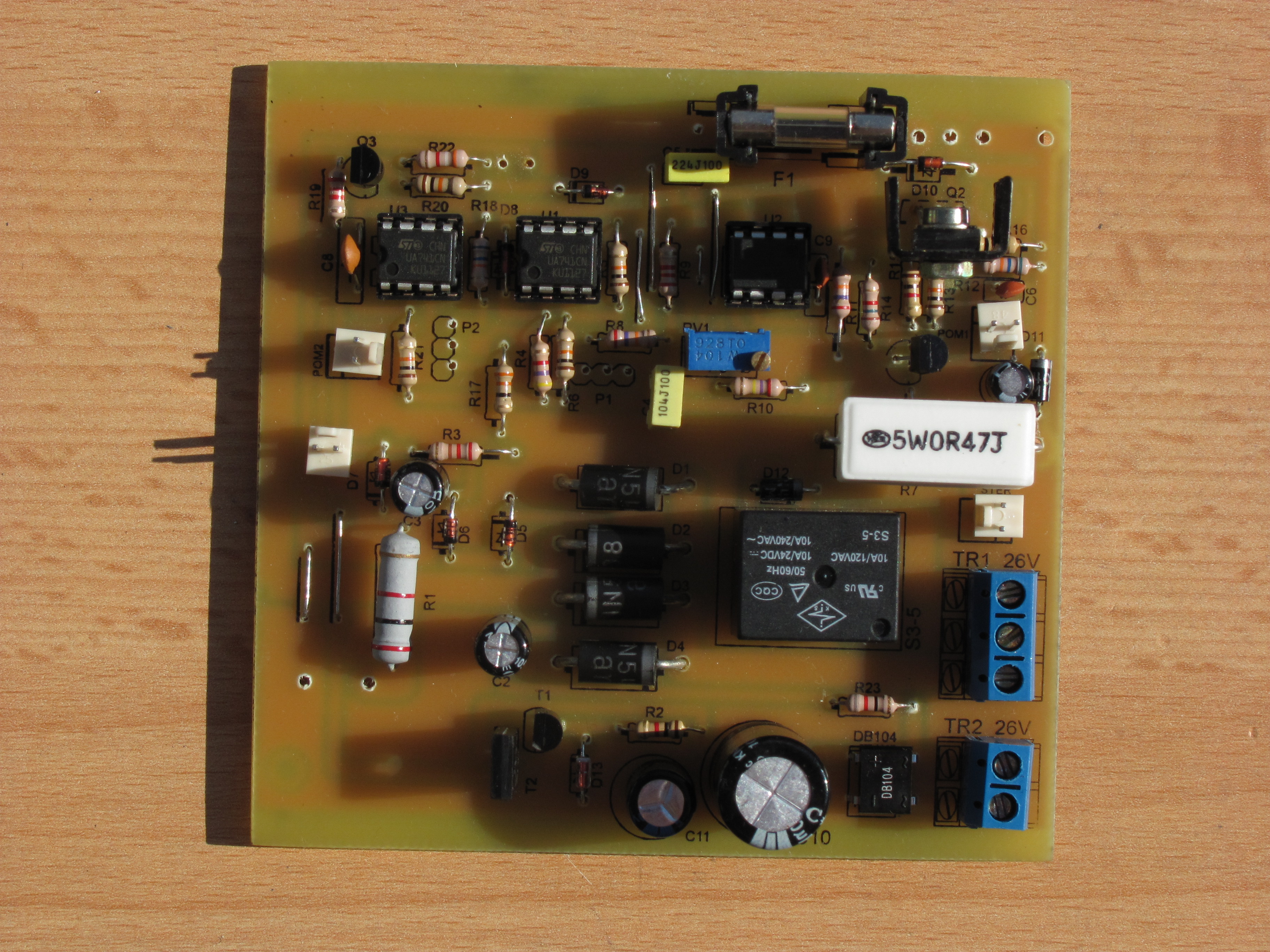
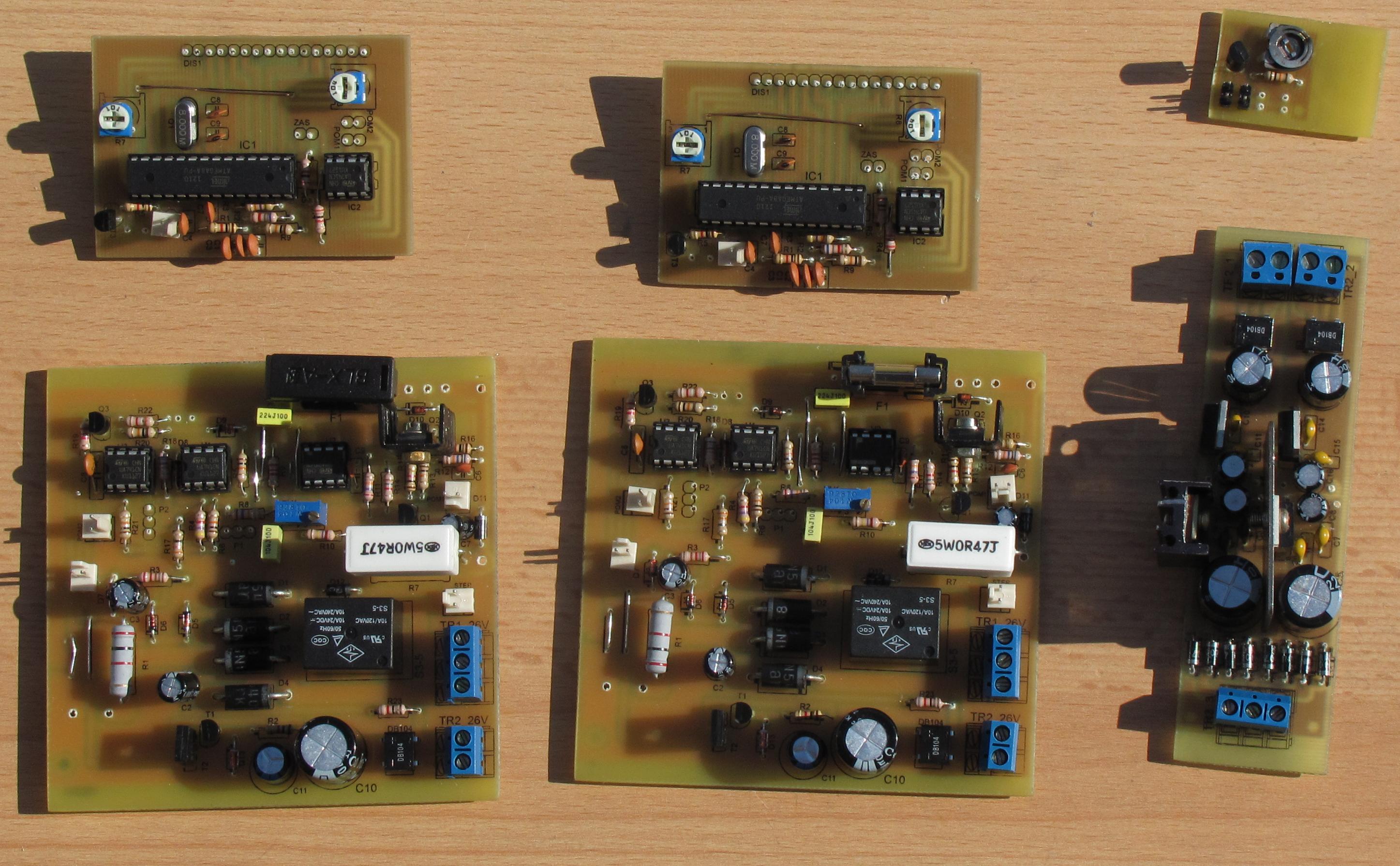
Schematic, PCB and program written in Bascom useful for making the meter, can also be found in the attachments to the original thread. To measure the current, voltage drop on the R7 resistor is used. To measure fixed current limitation, voltage of the slider of potentiometer P2 is used.
The meter was based on microprocessor Atmega8 and LCD display compatible with HD44780 with blue backlight. It is also responsible for switching the windings. On and off voltage of the relay should be entered in the program. It should be also calibrated, after uploading the program, check the meter reading with the multimeter reading and use the ratio to calculate and enter the appropriate number into the program. Pictures below show the power supply with unscrewed upper lid.
In fact, this power supply consists of two controlled power supplies in one housing with additional votlages 5V and 12V. Those power supplies are independent and all four voltages do not have any connection. Boards were designed in a way so that they can be used for construction of a single power supply.
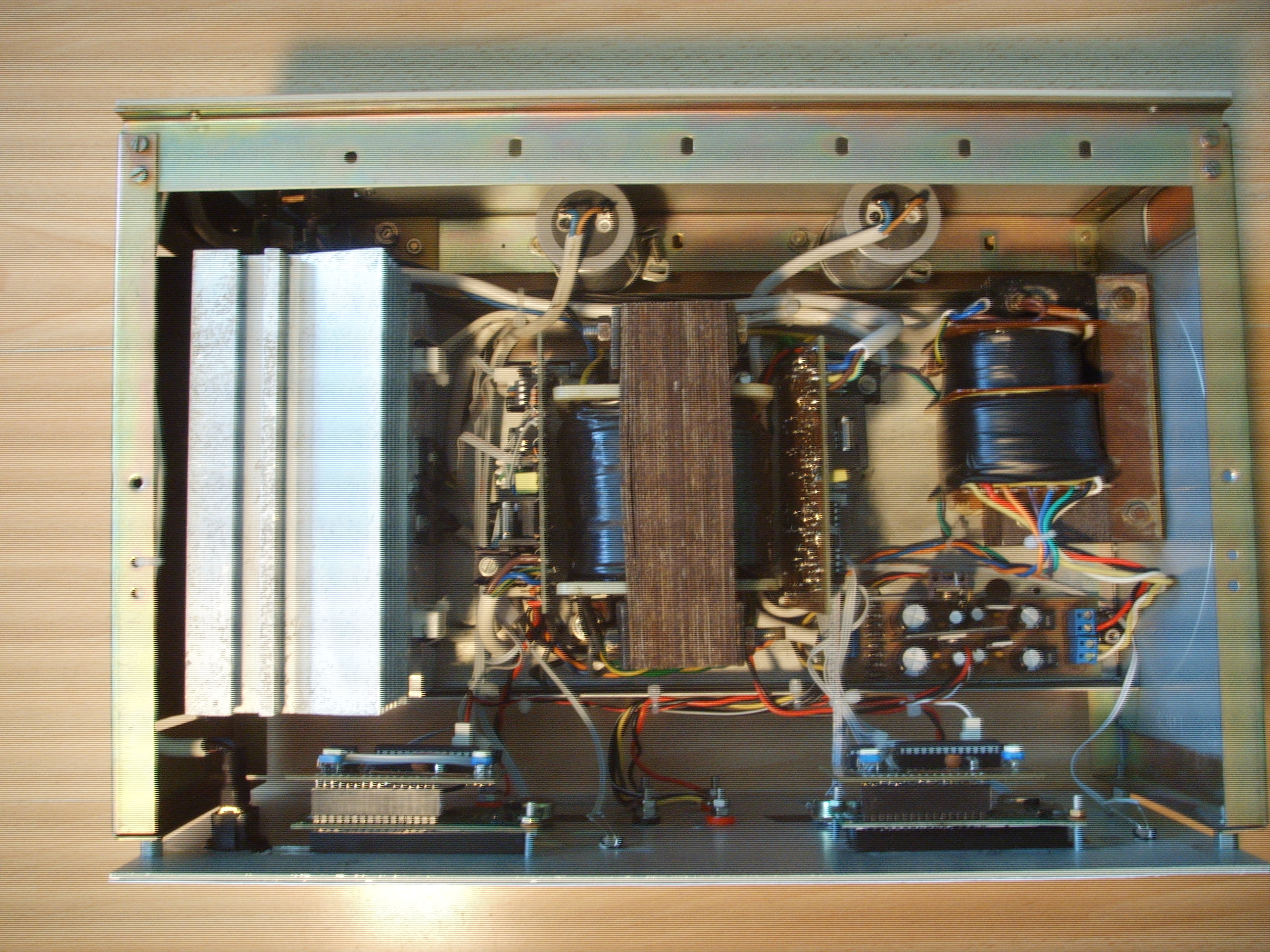
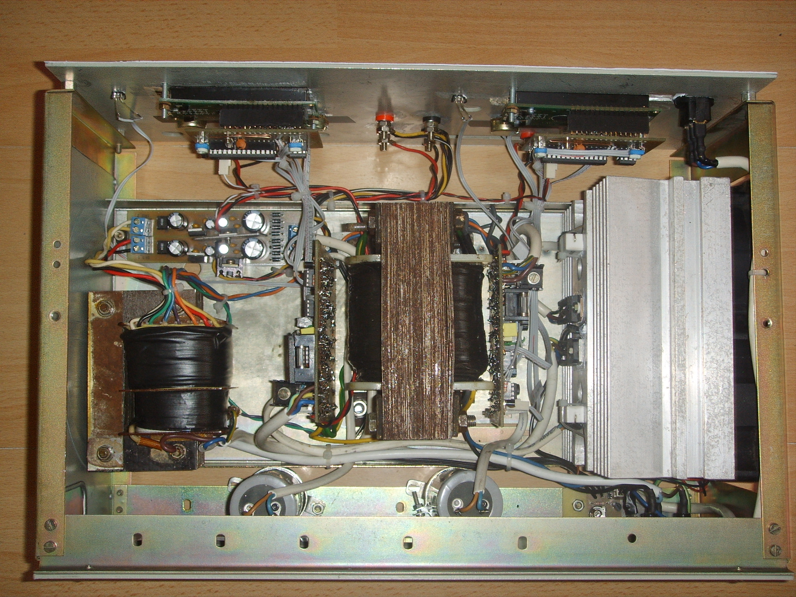
Main transformer is placed in the centre. Heat sink and auxiliary transformer had the similar weight, so that they were placed „symmetrically”, because the housing is equipped with a handle. That makes the device portable.
Link to original thread (useful attachment) - Zasilacz warsztatowy 2 x 0-30V / 0-3A