Continue to Site

Welcome to EDAboard.com

Welcome to our site! EDAboard.com is an international Electronics Discussion Forum focused on EDA software, circuits, schematics, books, theory, papers, asic, pld, 8051, DSP, Network, RF, Analog Design, PCB, Service Manuals... and a whole lot more! To participate you need to register. Registration is free. Click here to register now.

Analog amplifier with gain switchable between +1 and -1

Status
Not open for further replies.

hmalissa

Junior Member level 2
Joined
Apr 21, 2010
Messages
23
Helped
0
Reputation
0
Reaction score
0
Trophy points
1,281
Location
New Jersey
Activity points
1,492
I'm looking for a circuit that would allow me to invert the sign of an analog signal with a digital control signal.
I was thinking of building a unity gain amplifier and an inverting amplifier with gain -1 with 2 op amps, and use a MOSFET or such to switch between them. Does anyone have experience with such a circuit?
Also, I'd need fairly high precision, since I'm looking for a small difference in 2 larger signals.
The switching interval would be at least 4ms.
I think this is a very simplified version of a lock-in detector, is that right?
 

Thank you very much pointing out the analog multiplier to me. I did some reading and I believe that some kind of analog multiplier or voltage controlled amplifier is close to what I need.
But my control signal that switches the sign is a digital TTL signal. How can I build a sign multiplier that works with a digital input?
 

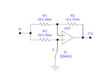
Below is a circuit using one op amp that will either invert or non-invert the signal depending upon the position of S1 (S1 closed is inverting).

S1 can be an analog switch controlled by a digital signal.

Note that R1 and R2 determine the inverting gain so need to be matched if you need the gain exactly at -1. You can make R2 a pot to adjust it exactly to match the non-inverting gain if you need to.

What is the highest frequency of the analog signal?

Invert-Noninvert Amp.gif
 
Thanks a lot, this is very helpful!
The highest frequency is 1kHz, so the circuit doesn't have to be very fast.
So S1 would be some kind of relay?
 

At 1kHz just about any standard op amp should work. Note that the power supplies require a voltage greater than the plus and minus input voltage peaks. How much greater depends upon whether it is a standard or rail-rail type op amp.

S1 can be a mechanical relay or analog solid-state switch. Note that the ON resistance of the switch has an effect on the inverting gain. You can minimize the effect by using a low resistance switch and/or increasing the value of R3. Also the switch must tolerate the plus and minus peak input voltage.
 
Last edited:

But my control signal that switches the sign is a digital TTL signal. How can I build a sign multiplier that works with a digital input?
Apparently you did not read the linked posts. I was exactly referring to circuits multiplying a digital with an analog signal.
 

Status
Not open for further replies.

Similar threads

Part and Inventory Search

Welcome to EDABoard.com

Sponsor

Back
Top