Continue to Site

Welcome to EDAboard.com

Welcome to our site! EDAboard.com is an international Electronics Discussion Forum focused on EDA software, circuits, schematics, books, theory, papers, asic, pld, 8051, DSP, Network, RF, Analog Design, PCB, Service Manuals... and a whole lot more! To participate you need to register. Registration is free. Click here to register now.

paralleling discontinuous or transition mode PFC

Status
Not open for further replies.

Johansen

Member level 4
Joined
Feb 10, 2008
Messages
76
Helped
13
Reputation
26
Reaction score
10
Trophy points
1,288
Activity points
1,844
I want to make a transition mode PFC for perhaps tens of kilowatts, running off 120 or 240vac, output 360-400Volts as standard.
to keep components resonable given the availability of power, at 120vac the supply only needs to deliver half the power at 240 vac.

so the power limits are more of a current limit rather than a power limit, lets make it 30 amps.

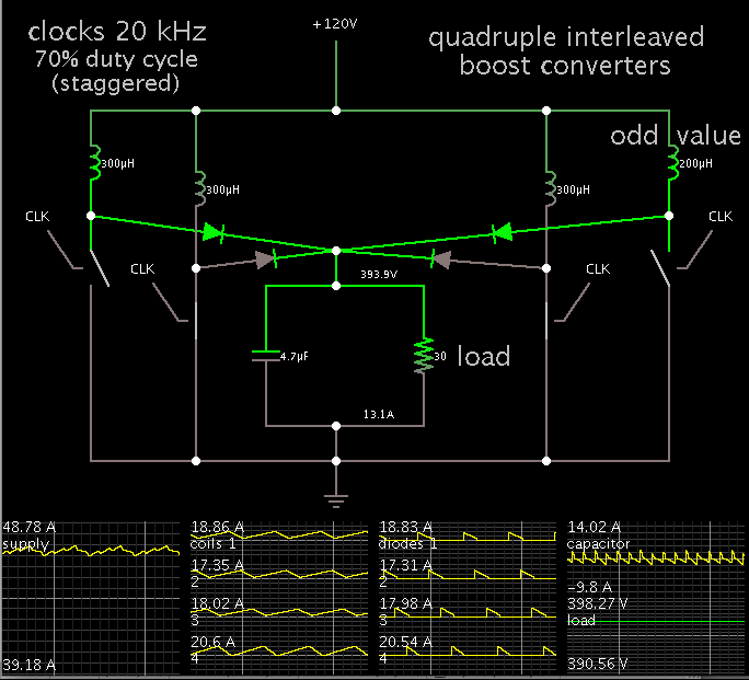
normally this would be done with a dual interleaved CCM boost but i'd rather have more phases and use a transition mode high frequency design, primarly because i have a lot of ferrite E cores available.

So i was thinking, i can take the L6562 or equivalent transition mode boost converter and drive multiple slave components by simply wiring the error amplifier for a gain of -1 and feeding it from a master error amp (i would use a discrete opamp on a separate card, to have more control over the system as well as providing redundancy, and making the total output power of the system modular)

my question is, due to the ESR and ESL of the single low value capacitor fed from the single phase ac grid, i could see in my mind all of these Transition mode converters would end up lumping together and running at one frequency.
one way to force them all to run at a different frequency i suppose would be to make the inductor values all differ by at least 1%

so i've been trying to come up with creative ways to force the converters to oppose each other.. and i can't think of any. due to the duty cycle ranging from 10% to 95%, there's no good way to hook up passive components to force them all to run anti-phase.
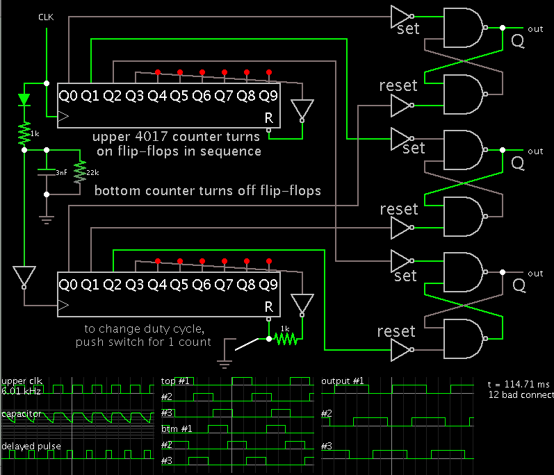
one idea i came up with was to make a ring oscillator from inverting schmitt triggers and wire the output to OR gates, and then hook that into the inductor current sense, so the TM mode converter would not switch on until the master oscillator allowed it too..
but that doesn't work because the duty cycle needs to be as high as 99%, not to mention the frequency is changing as well.

so i'm thinking its probably acceptable to just eat the beat frequencies and just let them all run at their own freq, the reduction in input and output current ripple from just three of them free running in parallel is more than adaquate.. with upwards of 10 of them running in parallel i think effectively there would be zero current ripple on the line. --unless they all end up running at the same frequency.

any thoughts?

--the current is naturally shared according to the tolerance of the onboard multiplier. since each chip will get the exact same voltage fed from the error amp (by nature of the -1 gain each would be wired for, and the same voltage to the ac voltage sense pin (since they would all run in parallel)
then the output of the multiplier should be within 10%.
each boost mosfet or igbt would have its own current sense resistor, so if you really wanted to get them all to share the current equally you could hook up a potentiometer to scale each individual error amp gain +/-10%
 

Achieving interleaving on TM converters is inherently tricky because TM is a variable frequency design. If the inductor values are different between phases, then it's not possible to maintain a perfect current sharing, perfect TM operation, and perfect phase/frequency lock. So when designing a controller, you have to trade off a bit, and make sure your inductors are as matched as possible.

TI makes an interleaved TM PFC converter, the UCC28063, which implements interleaving by not using actual current mode control, and instead it uses on time control, and it has some internal controller for maintaining 180 phase shift between the phases. They don't explain how that control works, but it likely involves a simple PFD to adjust the relative on times of the two phases. This approach could, in theory, be applied to an arbitrary number of phases, but unfortunately the UCC28063 has no means of synchronizing with other controllers.

It's hard to tell how allowing multiple phases to run asynchronously will work, especially if they interact with each other. Personally I would avoid it, especially if you want to keep input ripple low enough to pass regulations. One approach would be similar to what TI does. Have one global voltage error amp whose output defines the setpoint for the peak current in each phase. However, for each phase, allow for a slight modulation of this setpoint, which is controlled by some synchronizing controller which looks at the phase/frequency of all outputs. Phases running a bit too fast should have their setpoint increased, while phases running a bit too slow should have their setpoint decreased. This would probably be best implemented with a powerful MCU.
 

the solution: one low value resistor, sized such that the average dc current flowing out of the bridge rectifier produces a voltage approximately equal to 10% of the individual phase's current sense resistor. in this way the triangle wave of the boost inductor current is riding on top of the dc +ac current flowing through the sum of n phases. said resistor can be made of any number of small discrete .25 or .5 watt resistors for nearly zero inductance.

Whenever two or three phases start riding together, the voltage across this resistor will have lower frequency harmonics of greater ac amplitude than the ideal case, in which were there say to be 5 converters in parallel, the voltage across this resistor would consist of triangle waves with a peak to peak ripple of 20% of the dc component, at a frequency of 5 times the individual boost switching frequencies.

this is almost worth patenting...

btw, these additional current sense resistors can be paralleled with an inductor to provide greater sensitivity, however the resistors need to be sized such that the Q is rather low, and the harmonics must not be able to excite any parasitic LC resonances in the range of the switching frequency, or its going to wreak havoc.
 

Since this is a brainstorming session, and thinking out-of-the-box is acceptable, I'm proposing a wild idea that may (or not) have any merit:

How about if you apply some very small amount of dithering to the voltage fed to each error amp?
 

the solution: one low value resistor, sized such that the average dc current flowing out of the bridge rectifier produces a voltage approximately equal to 10% of the individual phase's current sense resistor. in this way the triangle wave of the boost inductor current is riding on top of the dc +ac current flowing through the sum of n phases. said resistor can be made of any number of small discrete .25 or .5 watt resistors for nearly zero inductance.

Whenever two or three phases start riding together, the voltage across this resistor will have lower frequency harmonics of greater ac amplitude than the ideal case, in which were there say to be 5 converters in parallel, the voltage across this resistor would consist of triangle waves with a peak to peak ripple of 20% of the dc component, at a frequency of 5 times the individual boost switching frequencies.

this is almost worth patenting...

btw, these additional current sense resistors can be paralleled with an inductor to provide greater sensitivity, however the resistors need to be sized such that the Q is rather low, and the harmonics must not be able to excite any parasitic LC resonances in the range of the switching frequency, or its going to wreak havoc.
I'm not seeing what this could accomplish aside from a measurement of HF ripple. Just observing the summed ripple can't tell you which boost phase needs to be adjusted in order to keep it low.

Since this is a brainstorming session, and thinking out-of-the-box is acceptable, I'm proposing a wild idea that may (or not) have any merit:

How about if you apply some very small amount of dithering to the voltage fed to each error amp?
Dithering will always keep peak spectral power lower, both with single and multiphase converters. However it won't be effective as having all phases frequency locked and phase interleaved, and then applying global dithering to all phases.
 
Last edited:

All of the L6562 chips or equivalent are grounded to the common point ground, the extra dc bias with ac ripple is thus added to all of the current sense resistors, and this voltage is not low pass filtered, in fact we can put an inductor across this resistor to cause increased sensitivity. (provided the Q is rather low such that the instantaneous negative transient is not much more than say a few tens of millivolts)

because the ac ripple across this master current sense resistor is in phase and is not filtered, whenever two phases get close to each other, one of them will be forced to turn off sooner than it would have without it. (the ac ripple being a function of how close they are all to each other)


Here is a scenario:
10 phases in parallel, each with a .1 ohm current sense resistor, and on average they trip at 5 peak amps.

If they are all in phase, they would sum to form a triangle wave with 50 amps peak to peak.
so we put a .001 ohm resistor between all 10 phases and ground.

Ideally, they all space themselves out properly and across this resistor we get 25 millivolts of dc (corresponding to 10 x 5 amp peak triangle waves thus 25 average amps if my math is right) (25 average amps at 250vac is ~6 KW)

and on top of this 25mv dc is about 2.5 mv of ac ripple at 10 times the nominal switching frequency.
whenever two or three phases start creeping into each other, this 2.5mV of ac ripple is going to increase quickly, and decrease in frequency, depending on how you look at it. this ac ripple is what causes the individual phases to turn off sooner, because its added on top of all of the current sense resistors, we don't need to know which one is drawing too much current or running faster or slower than the other.

in fact we can add this voltage to the current sense trip comparator differently as well, we can capacitively couple it into the current sense pin as well, fed from a current transformer. thus we would be adding only the ac component.

does this make sense? i can draw the schematic if you want.
 

If operating in CCM, then it is not so crucial that inductor values match, however that is when their ohmic values become more predominant.

To illustrate the concept, here is a quadruple interleaved boost converter (idealized):


The load draws 5kW.

It requires peaks of about 19 A through each of 4 coils.

Duty cycle is 70 percent.

Notice the last coil has a much different Henry value from the others. Yet they all contribute about the same share of the load.
 

All of the L6562 chips or equivalent are grounded to the common point ground, the extra dc bias with ac ripple is thus added to all of the current sense resistors, and this voltage is not low pass filtered, in fact we can put an inductor across this resistor to cause increased sensitivity. (provided the Q is rather low such that the instantaneous negative transient is not much more than say a few tens of millivolts)

because the ac ripple across this master current sense resistor is in phase and is not filtered, whenever two phases get close to each other, one of them will be forced to turn off sooner than it would have without it. (the ac ripple being a function of how close they are all to each other)


Here is a scenario:
10 phases in parallel, each with a .1 ohm current sense resistor, and on average they trip at 5 peak amps.

If they are all in phase, they would sum to form a triangle wave with 50 amps peak to peak.
so we put a .001 ohm resistor between all 10 phases and ground.

Ideally, they all space themselves out properly and across this resistor we get 25 millivolts of dc (corresponding to 10 x 5 amp peak triangle waves thus 25 average amps if my math is right) (25 average amps at 250vac is ~6 KW)

and on top of this 25mv dc is about 2.5 mv of ac ripple at 10 times the nominal switching frequency.
whenever two or three phases start creeping into each other, this 2.5mV of ac ripple is going to increase quickly, and decrease in frequency, depending on how you look at it. this ac ripple is what causes the individual phases to turn off sooner, because its added on top of all of the current sense resistors, we don't need to know which one is drawing too much current or running faster or slower than the other.

in fact we can add this voltage to the current sense trip comparator differently as well, we can capacitively couple it into the current sense pin as well, fed from a current transformer. thus we would be adding only the ac component.

does this make sense? i can draw the schematic if you want.
I think I get the idea, though a schematic would be helpful. I still don't see how this approach would result in feedback that forces interleaving, rather than some chaotic oscillation.

Another thing is that in interleaved converters their source and loads must be connected directly to each other, so using a resistive shunt in the ground paths wouldn't work. Using a current sense winding on each inductor would though.
 

I wonder if this has possibilities...

Illustrating how to provide equally spaced pulses to each boost converter.


Two 4017 IC's (decade counter) accept incoming clock pulses. They distribute pulses to flip-flops, which are simple Set/Reset type. (3 are shown but any number can be used.)

The upper 4017 turns the flip flops on in sequence.

The bottom 4017 turns them off. A simple delay circuit (at left) creates a variable duty cycle (depending on component values).

At the moment of snapshot it was yielding 60% duty cycle. The timing pulses had to be in the proper sequence.

It is possible for the pulses to get out of sequence. Then the duty cycle might become 36 %, or 93 %.
There ought to be a means to reset the bottom 4017 during each cycle, so that the pulses stay in sequence.
 

Another thing is that in interleaved converters their source and loads must be connected directly to each other, so using a resistive shunt in the ground paths wouldn't work. Using a current sense winding on each inductor would though.
keep in mind that the inductor sense coil turnsthe switch on, the resistive current sense trurns it off.

Yes, chaotic oscillation might result if the auxiliary current sense resistor is far too large, an additional 10% is all I figure you need
 

another possibility is adding the current ripple to the error amp of all the phases.

note that the total current ripple would have to be added to the error amps after the compensation network, as the information won't be able to flow through said network (seeing as the information you want is around 1/2 times the number of phases times the nominal switching frequency)

so the way i see it, injecting it into the current sense turn off pin is the fastest and easiest way of switching off whichever converter is on at the time when two or three or more phases are running into each other. (seeing as the current sense comparators have a fixed 200-400ns delay rather than a variable gain bandwidth product)

hmm.... these TM mode PFC converters should lend themselves to fixed synchronous operation..
 

**broken link removed**

hope this helps. i'll throw up a real diagram later when i figure out if it works or not.

in the first image it should be clear how you can parallel any number of smps drivers without additional loading of the master error amp.
 

I haven't installed the boost inductors but I'm about to fire up 3 of these things in parallel.
the schematic is straight out of the data sheet, but the current sense resistors are connected in parallel as in the above diagram.
turns out heatsinkable resistors are more expensive than mosfets.
I'm using 22mOhm p50no6 mosfets as current sense resistors.

i have not yet built the master error amplifier.
**broken link removed**
 

turns out heatsinkable resistors are more expensive than mosfets.
I'm using 22mOhm p50no6 mosfets as current sense resistors.

**broken link removed**

Yes, I've found this also...surprising.

Your Mosfet idea sounds intriguing. The only problem I would see with that is that RDSon changes with temperature
 

the 50n05 fets i'm using are actually obsolete, but they appear to be similar to the 50n06 which is still available.
It would appear there is a 50% increase in resistance from 33C to 120C
which for this application is fine, because it will provide natural current limiting, although a less steep curve would be preferred.
 
Last edited:

well i had three of these things,
and then one of them died when something shorted out on the board.
and then i compromised the other two by sending 15 volts into the multiplier. (internally clamped at 5 volts).. and they work sometimes.

but the two that work partially seem to at least prove the concept, they almost never both switched on at the same time, though the frequency varied quite a bit, and there was quite a bit of chaos (likely probably due to the length of the control wires i soldered to the board)
so i'll be back again when new L6562's show up.
but i'm confident the topology works.
 

It's cool to see you're still working on the concept, I missed when you first posted that schematic. I think you must have drawn your compensator wrong... R7 and it's parallel cap aren't doing anything when connected that way. Also your comparators are set up with negative feedback, meaning they won't function as comparators.... overall I can't see how the schematic forces interleaving, or transition mode control.
 

the 'current turn off comp' shown connected to the fet is internal to the L6562 --its + input is connected to the output of the multiplier
(the output actually feeds into the output flip flop)
The opamp that is wired as a -1 gain, is the internal error amplifier.

i don't know what i was thinking when i put c7 where it is.

the method by which it forces interleaving is in the current sense resistor.. notice how they are wired up. they are all on top of one resistor (actually a bunch of discrete ones in parallel) such that the master current ripple is "on top of" 'all' of the current sense resistors.

in order to force the converters to share current, i have to wire the internal error amplifiers for a -1 to -10 gain, in order that the offset error (which is on the order of 1-5 mV) ensures that all of the (n) l6562's receive the same voltages going into the mulitplier. a -10 gain means that they should all be +/-25 mv. (against a 1 volt scale, this is ~3%)

this means that i have to invert and amplify the control signal against a voltage reference, which i believe the "generic fast opamp" does. it uses the 2.5 volt referance which is extracted from (n) 6562's via those two 100K resistors.
this averages the voltage referance from all of the 6562's and negates the need for an external voltage referance.

the 6562 itself is forced transition mode, the fet always turns on whenever the ZCD pin is pulled negative.
 
Last edited:

**broken link removed**

There is some weird stuff going on here at the beginning of each 120 hz half wave.
There are a number of separate issues going on that cause this start up glitch.
number one being the error amplifiers were grounded, so the multiplier had 4.7 volts on one input, and almost nothing on the other input due to the very low input voltage, which is why they aren't sharing current equally, because under these conditions the multiplier doesn't have a linear output, and chip to chip its going to have a lot of variation.
also there's some variation between the input voltage divider. every chip should probably have a jumper to get the multiplier voltage from the same divider.

but its abundantly clear the concept works. the current sense resistors may need to be 70% and 30% rather than 50/50 as they are in both prototypes shown here.

I'm working out what the limits are for input peak to peak ripple.
when i just had 18uF or so on the input side of the two phase boost converter, the peak to peak ac ripple voltage was easily 50% on the capacitor.
(i have no idea how much current it was pulling). under this condition both phases will lump together almost perfectly in sync.

the input capacitor i believe has to be big enough to force the ac high frequency ripple voltage to be below 25% of the dc value or this will happen, when the current sense resistors are connected together at the half way point.

here is the 4 phase version:
**broken link removed**
 

I don't know if I had asked you this before, but how do you mill the traces into the blank copper board? Do you use a CNC machine?
 

Status
Not open for further replies.

Similar threads

Part and Inventory Search

Welcome to EDABoard.com

Sponsor

Back
Top